8. DAC
8.1. Overview
This example shows DAC conversions and waveform display in three working modes.
8.2. Board Setting
Output voltage at the specified pin. (Please refer to Pin Description )
If necessary, connect a jumper for VREF pin according to the HW design. (Please refer to Pin Description )
8.3. Running the example
Running log is shown in the serial terminal as follows
This is a DAC demo:
1. Direct mode
2. Step   mode
3. Buffer mode
Please enter the DAC mode code:
Select one of DAC working modes to start DAC conversion, and then observe the waveform through an oscilloscope
Direct mode
Please enter the DAC mode code: 1
Set DAC to output data in direct mode
DAC is outputting a triangle waveform in direct mode

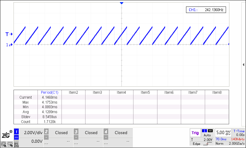
Step mode
Please enter the DAC mode code: 2
Set DAC to output data in step mode
DAC is outputting a saw tooth waveform in step mode
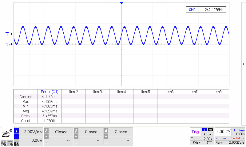
Buffer mode
Please enter the DAC mode code: 3
Set DAC to output data in buffer mode
DAC is outputting a sine waveform in buffer mode
8.4. Note
Exception exit
In step mode or in buffer mode, press the “space” key to abort the test, and then a test mode can be reselected.
In direct mode, press the “space” key to abort the loop after the test is finished, and then a test mode can be reselected.