42.2. OpENer Motor
42.2.1. 1.Overview
The OpENer Motor example is used to demonstrate the function of realizing remote motor speed control through the Ethernet/IP (EIP) protocol using OpENer.
42.2.2. 2.Preparation
42.2.2.1. 2.1 Hardware
A development board with Ethernet. Refer to the {ref}pin description <lab_board_resource> of the specific development board to view the Ethernet hardware.
==According to your development board, select RMII/RGMII and ethernet phy in the CMakeLists.txt==
A PC with a network port.
The TwinCAT3 software has adaptation issues with PC network cards. Some supported Intel network cards.
This program uses the BLM57050-1000 brushless motor of “Leisai Intelligence”, please refer to the Leisai Intelligence website for the specific parameters of the motor.
Board settings refer to the development board documentation Motor Pin related content
42.2.2.2. 2.2 Software
TwinCAT3.1(Build 4024.56)
42.2.3. 3. TwinCAT project settings
42.2.3.1. 3.1 Create a project
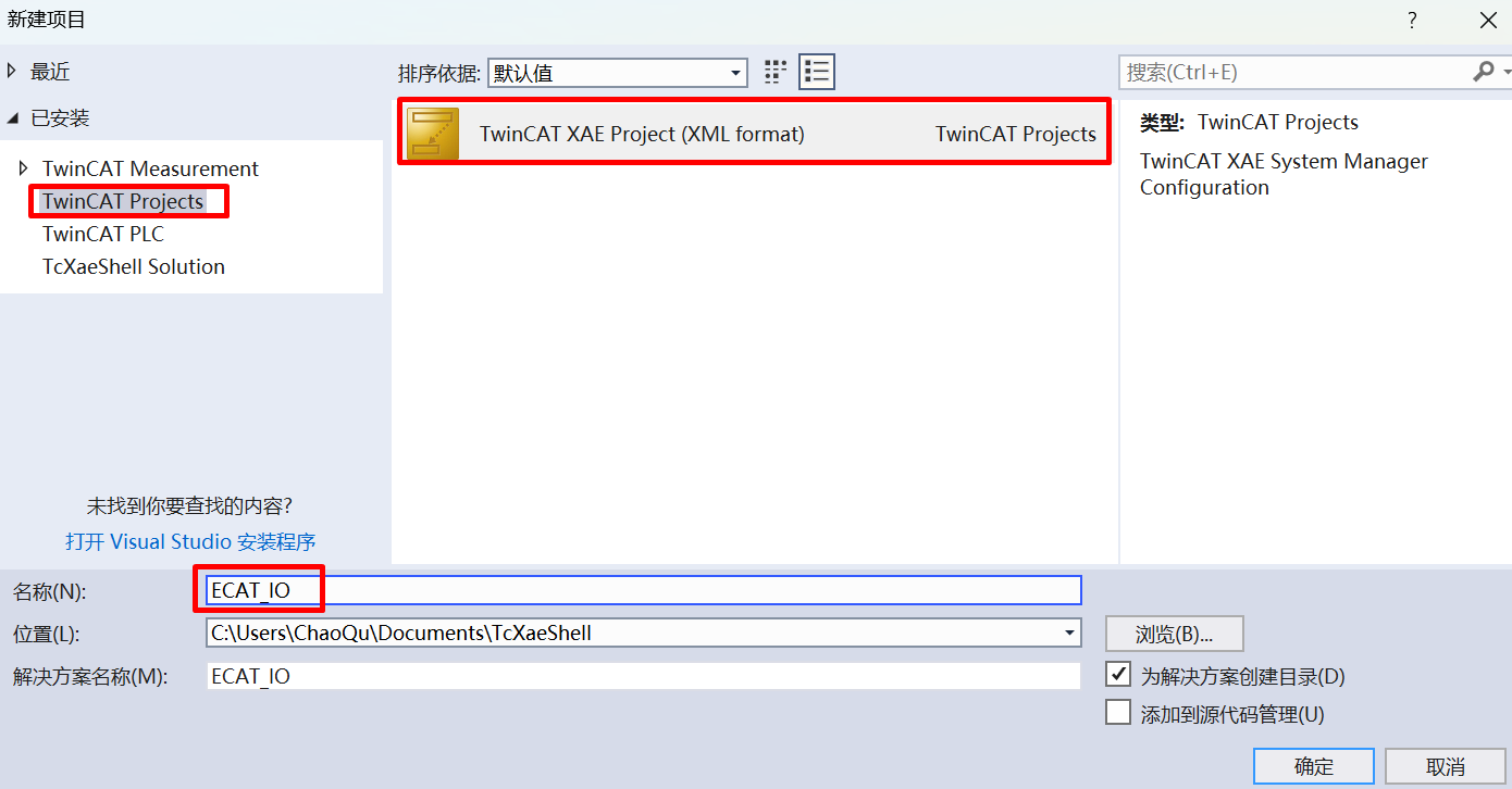
Open the TwinCAT software and select File -> New -> Project.
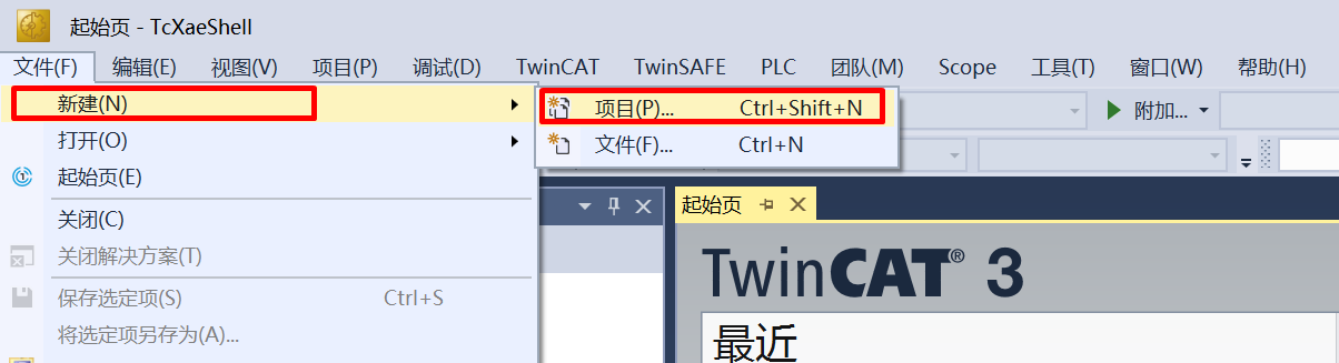
Select TwinCAT Project, name it and click OK.
42.2.3.2. 3.2 Software configuration
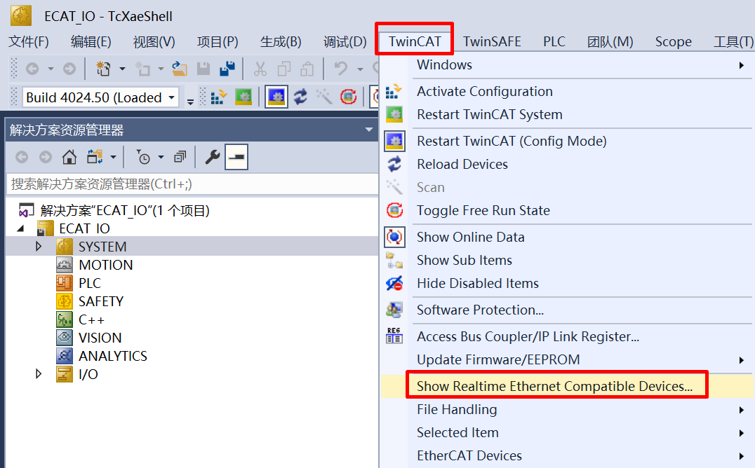
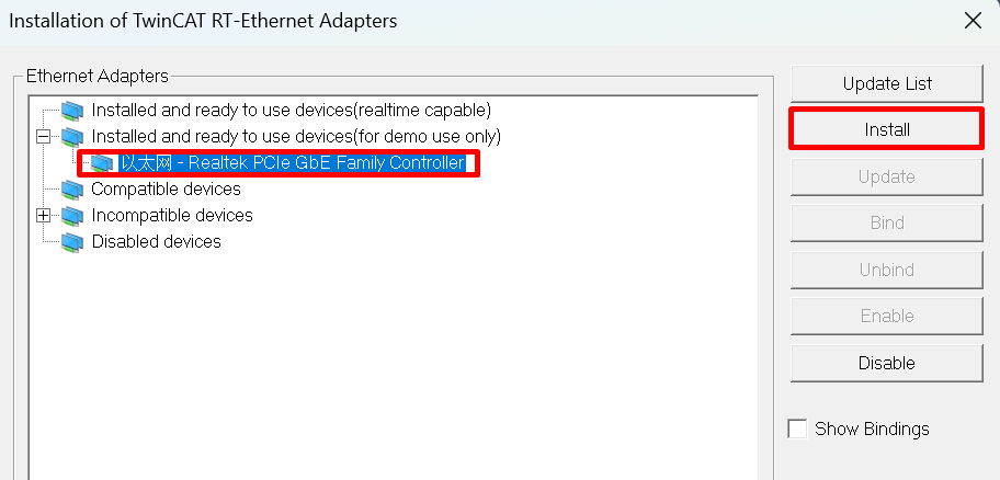
Update the network card driver (required when using for the first time).
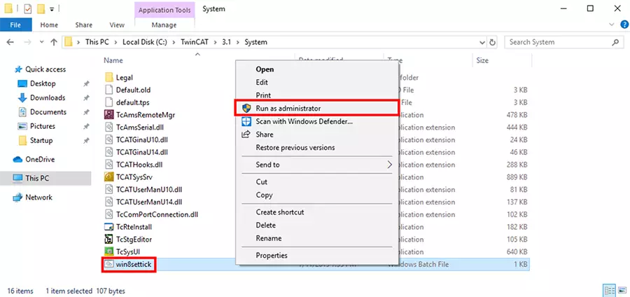
Clock setting When the software is running, the following error may be encountered: It is necessary to run C:\TwinCAT\3.1\System\win8settick.bat with administrator privileges.
Init4\RTime:Start Interrupt:Ticker started >> AdsWarning4115 (0x1013,RTIME:system clock setup failed)
42.2.3.3. 3.3 Add EIP Scanner
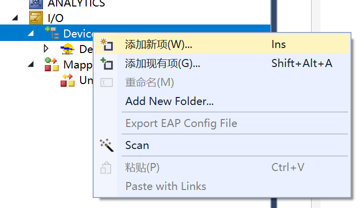
Click on Device, right-click to add a new item.
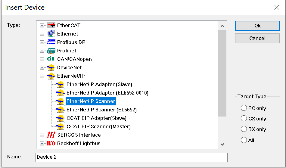
Select EIP Scanner.
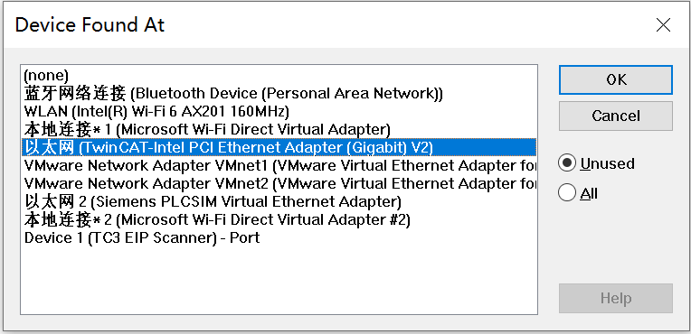
Select the network card after the driver is updated.
Configure the IP address.
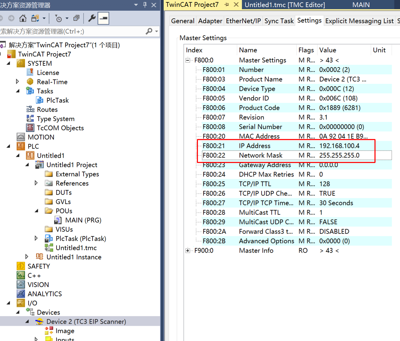
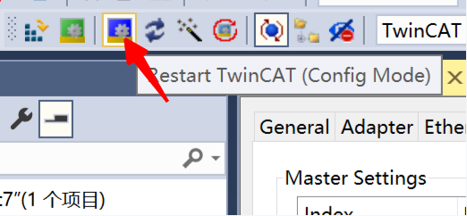
Re-enter the configuration mode to make the IP configuration in the previous step take effect.
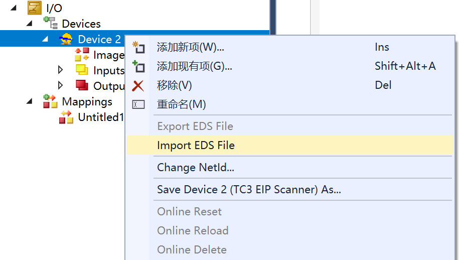
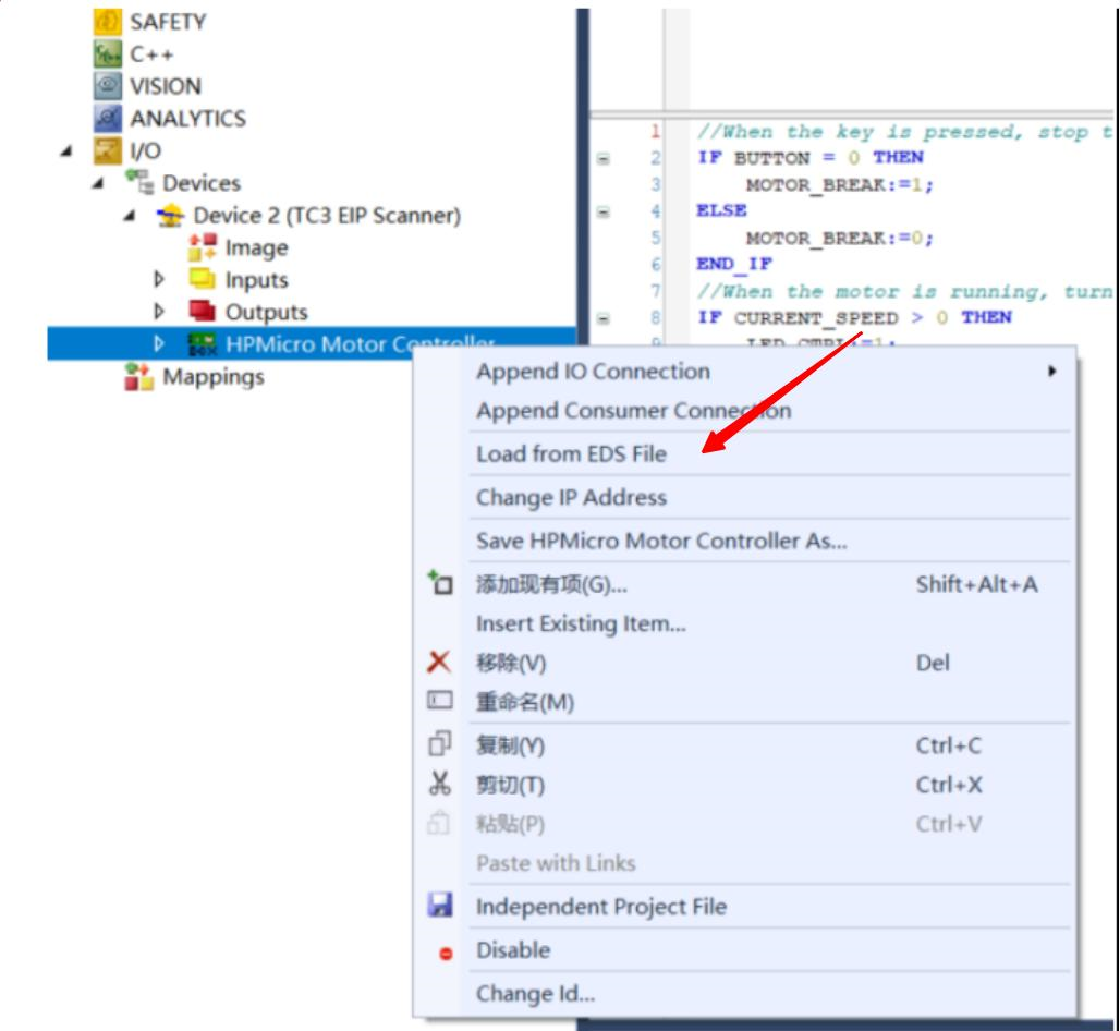
42.2.3.4. 3.4. Add EDS file
Right-click on EIP Scanner and select import EDS file. Select opener/opener_blinky_app.eds.
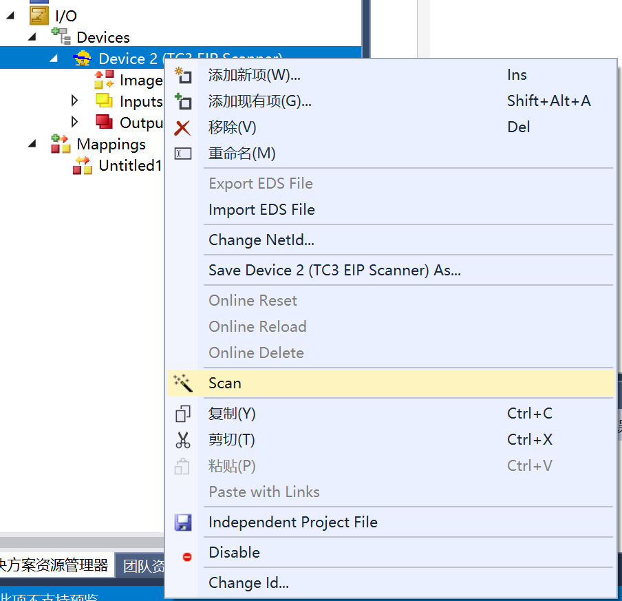
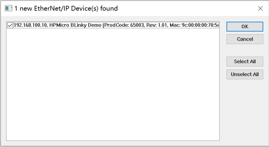
42.2.3.5. 3.5. Scan devices
Right-click on EIP Scanner and then scan.
Add a device.
42.2.3.6. 3.6 Add IO connection
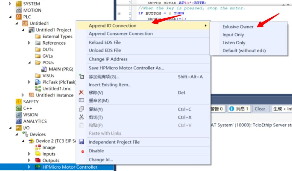 If there is no
 Exclusive Owner is the combox, specify the eds file manually.
42.2.3.7. 3.7 IO operation
For input IO, press the button KEYA on the evaluation board, and the value of Input/Key State changes.
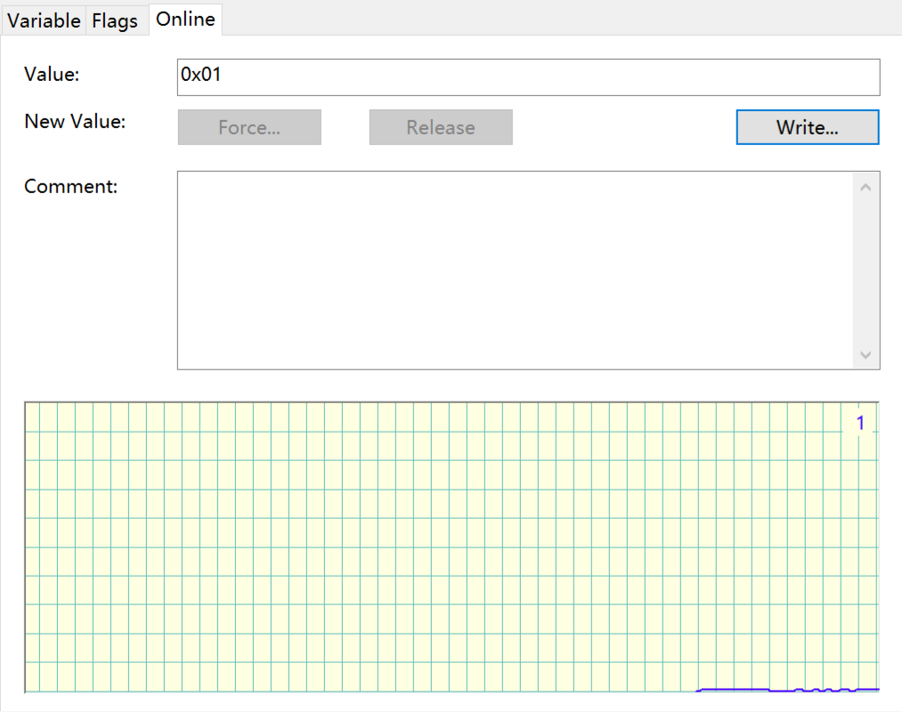
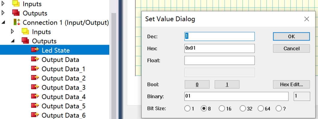
For output IO, right-click on Led State, select Online, and click Write to write a value. When writing 1, the LED on the development board lights up. When writing 0, the LED on the development board turns off.
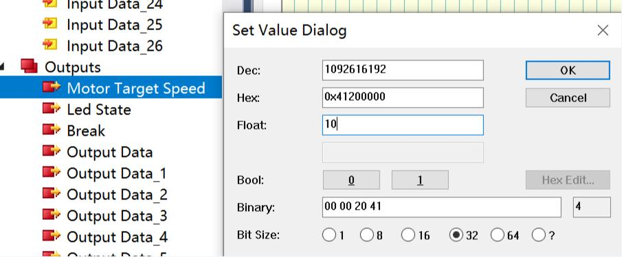
For output IO. Right-click “Motor Target Speed”, select “Online”, and click “Write” to enter a value. The motor rotates according to the input value. Note that the upper limit of the motor speed is 35.
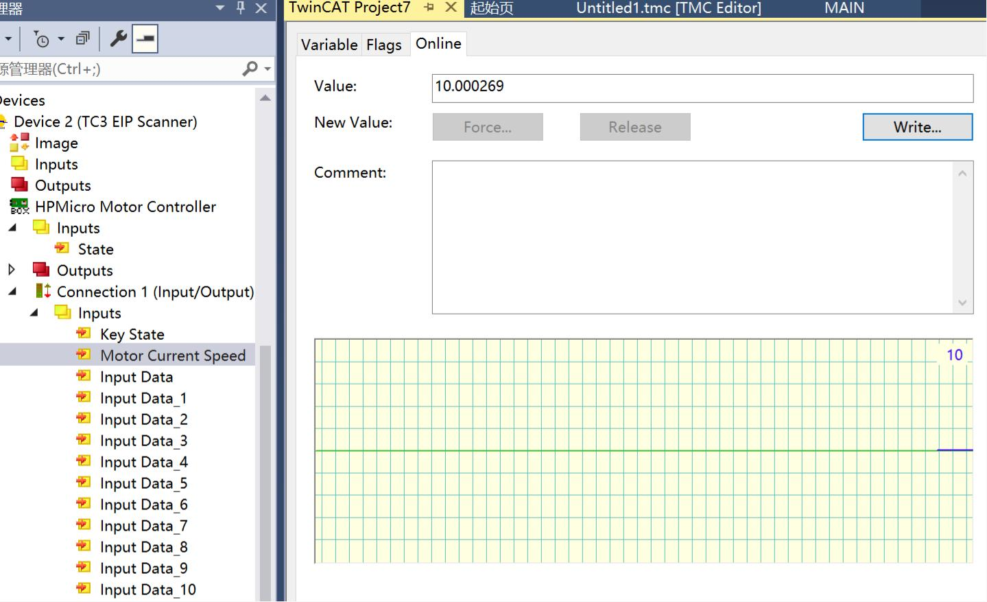
For input IO. Observe “Inputs/Motor Current Speed”, which shows the real-time motor speed.
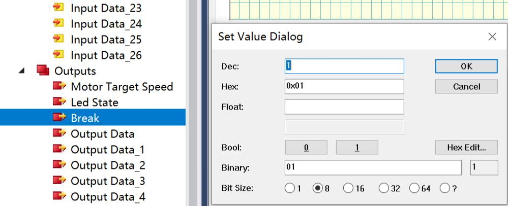
For input IO, right-click Break, select Online, and write values by motor Write. When inputting 1, the motor stops rotating. When inputting 0, the motor resumes the rotating state before stopping.
42.2.4. 6. Operation phenomenon
After the project runs correctly, the serial terminal will output the following information:
This is an Ethernet/IP demo.
LwIP Version: 2.1.2

Speed mode, motor run, speed is: 0.000000.
Enet phy init passed !
Link Status: Down
Link Status: Down
Link Status: Up
Link Speed:  100Mbps
Link Duplex: Full duplex
IPv4 Address: 192.168.100.10
IPv4 Netmask: 255.255.255.0
IPv4 Gateway: 192.168.100.1
Mesaage receieved from host!