24.8. STEP MOTOR FOC
24.8.1. Overview
The step motor foc project description Stepper motor control using vector modulation. - Use the FOC control algorithm
Trapezoidal acceleration and deceleration curves
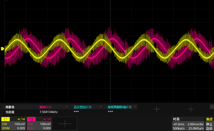
The current waveform is as follows, a sine wave with a phase difference of 90 degrees
24.8.2. Configurations
42 Stepper Motor, 24v, 50 Pair of Poles.
Stepper motor driver board 24V_STEP_NONE_2A .
plug J2 and J4
connect M1 to motor
Plugged into the driver board via the motor interface
24.8.3. Running the demo
The stepper motor switches forward and reverse speed without stopping, and the serial port prints speed information.
The serial console message is as follows:
step motor demo.
speed: 1 r/s.
speed: -2 r/s.
speed: 3 r/s.
speed: -4 r/s.
speed: 5 r/s.
speed: -6 r/s.
speed: 1 r/s.
speed: -2 r/s.
speed: 3 r/s.
speed: -4 r/s.
speed: 5 r/s.
speed: -6 r/s.
speed: 1 r/s.
speed: -2 r/s.
speed: 3 r/s.
Warning
Pay attention to the current size, when abnormalities occur, please cut off the power at any time
Pay attention to the temperature of the stepper motor in long-term operation.