5. HPM6300EVK
5.1. Overview
HPM6300EVK provides interfaces for most of the peripherals of the HPM6300 microcontroller, including 1 SD card slot, 1 USB Type-C interface, a 100M Ethernet port, CAN FD interface, etc., and expands NOR Flash, SDRAM and other external memories, and integrates an on-board debugger.

5.2. Hardware
HPM6360IPA MCU
Onboard Memory
16bit 256Mb (32MB) SDRAM
128Mb (16MB) Quad SPI NOR Flash
USB
USB type C (USB 2.0 OTG) connector x1
Ethernet
100Mb PHY
Others
TF Slot
CAN FD
FT2232
Expansion port
Motor control port
Raspberry PI extension port
Note
The sdram pins are multiplexed with the 15-20pin of the motor interface J26, so the motor interface and sdram can’t be used at the same time.
5.3. DIP Switch S1
Bit 1 and 2 control the boot mode
bit[2:1] |
Description |
|---|---|
OFF, OFF |
Boot from Quad SPI NOR flash |
OFF, ON |
Serial boot |
ON, OFF |
ISP |
5.5. Plug-in
The ADC/DAC reference voltage is selected as follows:
Connection
Description
J108[2, 3]
Reference voltage
5.6. Pin Description
SPI Pin:
Function
Position
SPI3.CSN
J28[24]
SPI3.SCLK
J28[23]
SPI3.MISO
J28[21]
SPI3.MOSI
J28[19]
I2C Pin:
Function
Position
I2C0.SCL
J28[13]
I2C0.SDA
J28[15]
ACMP Pin:
Function
Position
CMP.INN5
J26[7]
CMP.COMP_1
J26[8]
GPTMR Pin:
Function
Position
Remark
GPTMR2.CAPT_0
J28[40]
SENT decode input pin (idle low level)
GPTMR2.COMP_0
J28[35]
MCLK of i2s emulation
GPTMR2.COMP_1
J28[12]
LRCK of i2s emulation
GPTMR2.COMP_2
J28[16]
BLCK of i2s emulation
GPTMR2.COMP_2
J28[16]
SENT decode input pin (idle high level)
ADC16 Pin:
Function
Position
ADC16 Reference Voltage
J108[2]
ADC0.INA6
J28[38]
DAC Pin:
Function
Position
DAC Reference Voltage
J108[2]
DAC0.OUT
J26[11]
PWM Pin:
Function
Position
PWM2.P0
J26[14]
PWM2.P1
J26[13]
Ethernet PPS Pin:
Function
Pin
Position
ENET0.EVTO0
PC21
J28[19]
ENET0.EVTO1
PC20
J28[23]
ENET0.EVTI0
PC27
J28[22]
ENET0.EVTI1
PC26
J28[18]
UART pin:
The UART2 is used for some functional testing using UART, such as uart_software_rx_idle, uart_rx_timeout, uart_software_lin, MICROROS_UART, USB_CDC_ACM_UART, MODBUS_RTU etc.
Function
Position
Remark
UART2.TXD
J28[18]
UART2.RXD
J28[22]
UART2.break
J28[24]
generate uart break signal
TRGMUX pin for uart_software_rx_idle sample:
Function
Position
TRGM1_P4(PA24)
J28[16]
Motor Pin:
Refer to section DRV-LV50A-MP1907 Motor Driver Board for configuration
Tamper Pin:
Function
Pin
Position
Mode
TAMP.06
PZ06
J28[8]
Active Mode
TAMP.07
PZ07
J28[10]
Active Mode
CS Pin of i2s emulation:
Function
Position
Remark
PA07
J28[11]
the pin that controls SPI slave CS
ESP-HOSTED Pin
Function |
Position |
Note |
|---|---|---|
PA07 |
J28[11] |
RESET Pin |
PC13 |
J28[13] |
HANDSHAKE Pin |
PC14 |
J28[15] |
DATA_READY Pin |
BROWNOUT Interrupt Indicator Pin
Function |
Position |
|---|---|
PA07 |
J28[11] |
5.7. Board Known Issue
USB VBUS pin resistance issue
Impact
This issue may affect the Host’s ability to enumerate USB as a device.
Solution
Replace the 1kohm resistors R135 with 10ohm resistors.
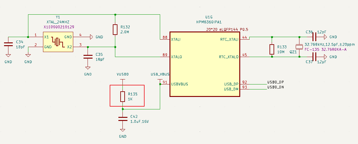
Revised Status
HPM6300EVKRevD has been revised, HPM6360-EVK-A3 and previous versions have this issue.
USB ID pin pull down resistance issue
Impact
When using USB OTG, this issue may affect the role recognition of USB connected device or connected host.
Solution
Remove the pull-down resistors R127, R128 from the CC port of the USB interface.
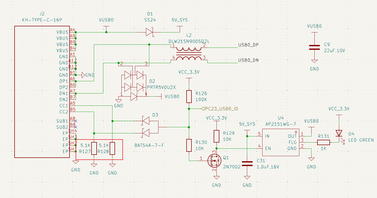
Revised Status
HPM6300EVKRevD has been revised, HPM6360-EVK-A3 and previous versions have this issue.