8. HPM6800EVK
8.1. Overview
The HPM6800 is a single-core flashless MCU running 600MHz. It has a 1MB continuous on-chip ram. Also, it provides various memory interfaces, including SDRAM, Quad SPI NOR Flash, SD/eMMC. It integrates rich audio and video interfaces, including LCD, pixel DMA, camera, and I2S audio interfaces.

8.2. Hardware
HPM6800 MCU (600MHz, 1MB SRAM)
Onboard Memory
512MB SDRAM (DDR3L 16bits)
16MB Quad SPI NOR Flash
16GB eMMC
Display & Camera
LCD connector
MIPI-DSI
MIPI-CSI
Camera (DVP)
Ethernet
1000 Mbits PHY
USB
USB type C (USB 2.0 OTG) connector x1
Audio
Line in
Mic
Speaker
DAO
Others
TF Slot
RGB LED
CAN
8.3. DIP Switch SW2
Bit 1 and 2 control the boot mode
bit[2:1] |
Description |
|---|---|
OFF, OFF |
Boot from Quad SPI NOR flash |
OFF, ON |
Boot from eMMC |
ON, OFF |
ISP |
8.5. Plug-in
The ADC/DAC reference voltage is selected as follows:
Connection |
Description |
|---|---|
J18 |
Reference voltage |
The eMMC voltage is selected as follows:
Connection |
Description |
|---|---|
J6 |
eMMC voltage selection (3.3V / 1.8V) |
Note
User should short VCCQ and 1.8V pin for eMMC testing
8.6. Pin Description
UART0 Pin:
The UART0 use for debugger console:
Function
Pin
Position
UART0.TX
PA00
DEBUGUART0
UART0.RX
PA01
DEBUGUART0
UART3 Pin:
The UART3 is used for some functional testing using UART, such as MICROROS_UART, USB_CDC_ACM_UART, MODBUS_RTU etc.
Function
Pin
Position
Remark
UART3.TX
PE15
P2[8]
UART3.RX
PE14
P2[10]
UART3.break
PE04
P2[24]
generate uart break signal
PUART Pin:
The PUART is used for low power mode testing, such as wakeup, etc.
Function
Pin
Position
PUART.TX
PY00
P2[32]
PUART.RX
PY01
P2[29]
SPI Pin:
Function
Pin
Position
SPI3.CSN
PE04
P2[24]
SPI3.SCLK
PE05
P2[23]
SPI3.MISO
PE06
P2[21]
SPI3.MOSI
PE07
P2[19]
I2C Pin:
Function
Pin
Position
I2C1.SCL
PE13
P2[5]
I2C1.SDA
PE12
P2[3]
ADC16 Pin
Function
Pin
Position
ADC0.INA8
PE16
J19[15]
GPTMR Pin
Function
Pin
Position
Remark
GPTMR2.CAPT_0
PE22
J19[9]
GPTMR2.COMP_0
PE23
J19[12]
MCLK of i2s emulation
GPTMR2.COMP_1
PE24
J19[10]
LRCK of i2s emulation
GPTMR2.COMP_2
PE26
J19[8]
BLCK of i2s emulation
Headphone interface
Function
Position
Standard
3.5mm headphone
J4
OMTP
Audio input interface
Function
Position
microphone
P1
DAO interface
Function
Position
DAO-SPK(left)
J9
DAO-SPK(right)
J10
Ethernet PPS Pin
Function
Pin
Position
ENET0.EVTO0
PD31
J20[7]
ENET0.EVTO1
PE10
P2[11]
ENET0.EVTI0
PE17
J19[16]
ENET0.EVTI1
PE19
J19[14]
CAN Pin
Function
Pin
Position
Output
MCAN3.TXD
PD15
U25[1]
CAN.H J13[3]
MCAN3.RXD
PD14
U25[4]
CAN.L J13[2]
MCAN3.STBY
PD13
U25[8]
Tamper Pin
Function
Pin
Position
Mode
TAMP.04
PZ04
P2[35]
Active Mode
TAMP.05
PZ05
P2[38]
Active Mode
TAMP.06
PZ06
P2[37]
Passive Mode
CS Pin of i2s emulation
Function
Position
Remark
PE27
J19[5]
the pin that controls SPI slave CS
CLOCK REF Pin
Function
Position
PD31
J20[7]
ESP-HOSTED Pin
Function |
Position |
Note |
|---|---|---|
PE11 |
P2[13] |
RESET Pin |
PE12 |
P2[3] |
HANDSHAKE Pin |
PE13 |
P2[5] |
DATA_READY Pin |
BROWNOUT Interrupt Indicator Pin
Function |
Position |
|---|---|
PE27 |
J19[5] |
8.7. Board Known Issue
USB VBUS pin resistance issue
Impact
This issue may affect the Host’s ability to enumerate USB as a device.
Solution
Replace the 1kohm resistors R18 with 10ohm resistors.

Revised Status
Not yet revised, HPM6800EVKRevD and previous versions have this issue.
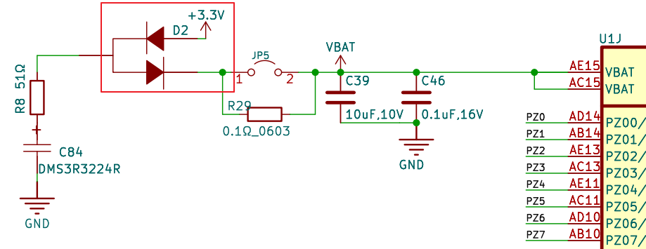
VBAT pin diode issue
Impact
The voltage rise of the VBAT pin is very slow and can only reach around 2.6V, so the related functions of the battery management domain may not function properly.
Solution
Replace the D2 diode with a Schottky diode, such as BAT54SWF.
Revised Status
Not yet revised, HPM6800EVKRevD and previous versions have this issue.