45.2. PLLCTLV2 SPREAD SPECTRUM
45.2.1. Overview
This example demonstrates the configuration of PLL spread spectrum.
Spread Spectrum Capabilities
Demonstrates how to configure spread spectrum modulation for EMI (Electromagnetic Interference) reduction.
- Spread Range
Default: 0.5%
Configurable through SS_RANGE macro
- Modulation Frequency
Default: 30 kHz
Customizable via MODULATION_FREQ macro
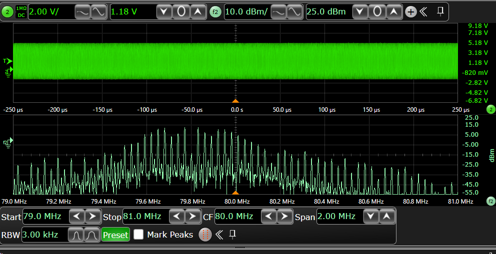
When the spread spectrum is enabled, on oscilloscope, similar FFT result is expected to be observed as following:
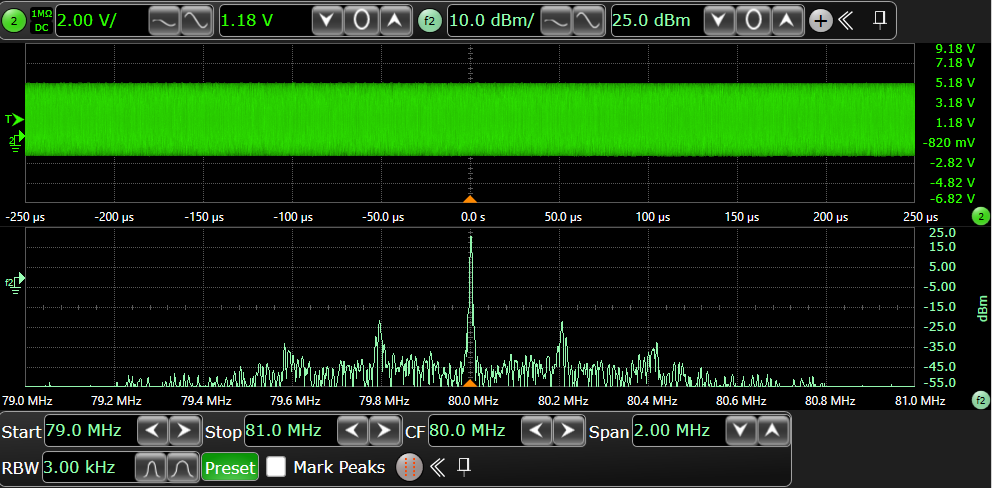
For comparison, the FFT result observed on the oscilloscope without spread spectrum enabled is shown below:
45.2.2. Board Setting
The configured PLL frequency can be observed via clk_ref pin by the oscilloscope, please refer to Pin Description for pin information of specific board.
45.2.3. Running the example
When the project runs correctly, the serial port terminal will output the following information:
PLLCTLV2 spread spectrum example
PLL2CLK0 @ 80000000Mhz spread spectrum has been enabled with range 0.5% @ 30000Hz, which can be observed on "J20[7]" pin by the oscilloscope

PLLCTLV2 spread spectrum example finished