51.6. PWM Synchronous Output
51.6.1. Overiew
PWM supports the multi-channel synchronous output function. This example demonstrates synchronizing three channels of PWM through the synt of the motor system, and the PWM waveforms are output via the corresponding pins of the MCU
51.6.2. Configurations
Oscilloscope
Install the serial terminal, view board information , and configure the serial terminal parameters
PWM_P0, PWM_P2, PWM_P4 pins Check the information according to the board model
51.6.3. Running the Demo
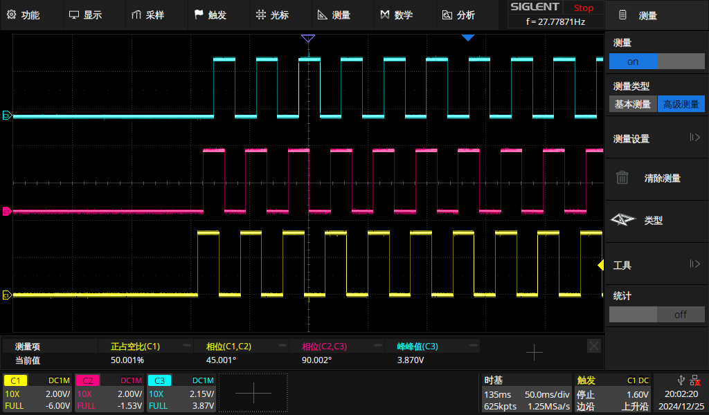
After power-on, the three channels of PWM output at the same time and in the same phase. Then different phase synchronous outputs are achieved through the trigger signal of synt
The output of P0 has a 45-degree phase difference from that of P2, and the output of P0 has a 135-degree phase difference from that of P4
Serial port printing information:
pwmv2 three pwm submodule synchronous example
choose PWM output channel [P0 P2 P4]


>> P0 P2 P4 generate waveform at same time
P0 is a reference


>> Phase different P0 P2 P4 is 45 degrees 135 degrees
P0 is a reference
test done
The obtained waveforms are shown in the figure
The yellow one is the output of P0<br> The pink one is the output of P2<br> The blue one is the output of P4
Note
Output the PWM waveform once, and if you observe the waveform again, you need to run the program again.