54.4.3. QEO_PWM_OUT
54.4.3.1. Overview
The QEO_PWM_OUT sample project demonstrates the functionality of the QEO (Quadrature Encoder Output) peripheral in controlling PWM output based on position information. QEO can receive position information either through software injection or from hardware (such as MMC), and generate corresponding PWM waveforms based on preset PWM commutation tables and resolution settings. This is commonly used in stepper motor control.
54.4.3.2. Working Process
This example demonstrates two working modes:
Software Position Injection Mode Configuration steps:
Initialize QEO module and configure PWM output
Configure 4-phase PWM output table:
Set PWM forced output state for each phase
Configure 4-step commutation sequence for motor phase control
Set resolution line count
Software position injection process:
Calculate position increment per step
Enable software position injection
Cyclically inject position values to switch PWM output
Wait for position calculation completion
Disable software position injection
Hardware Position Input Mode
In this example, the MMC (Motor Motion Control) peripheral provides position information to QEO, which then outputs corresponding PWM waveforms based on the received position information.
Configuration steps:
Initialize QEO module and configure PWM output
Configure 4-phase PWM output table:
Set PWM channels to non-forced output state (adjustable PWM duty cycle)
Configure safety mode output table
Configure hardware trigger and safety mode:
Set TRGM to trigger QEO entering safety mode
Automatically exit safety mode when new position arrives
Configure PWM in center-aligned mode
Configure MMC position output:
Connect MMC position output to QEO through TRGM
Configure MMC open-loop prediction mode
Enable motor timestamp function
54.4.3.3. Hardware Setting
Observe the output waveform on the specified PWM pins (Please refer to Pin Description section).
54.4.3.4. Running the Example
When the project runs correctly, you will observe the following:
Serial terminal output:
QEO PWM example
QEO generate PWM signal with software inject postion
QEO generate PWM signal with hardware(MMC) provide postion
PWM output waveforms:
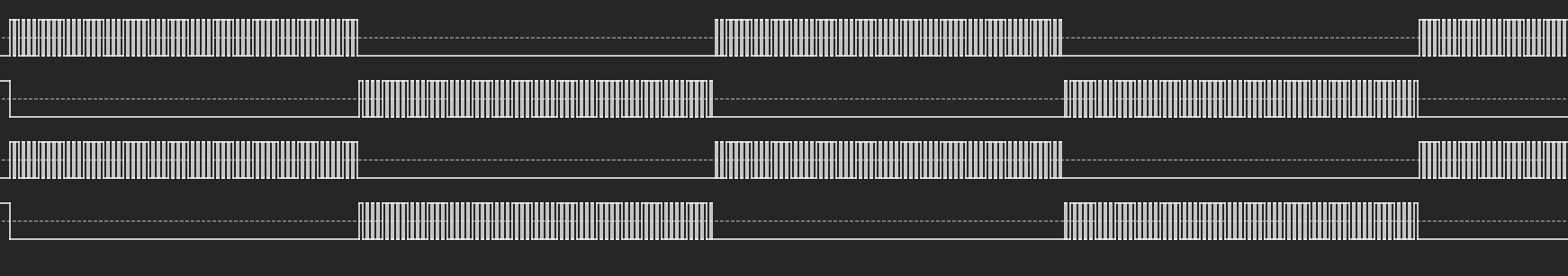
Using a logic analyzer, you can observe two different PWM waveforms:
Forced output waveform in software position injection mode:
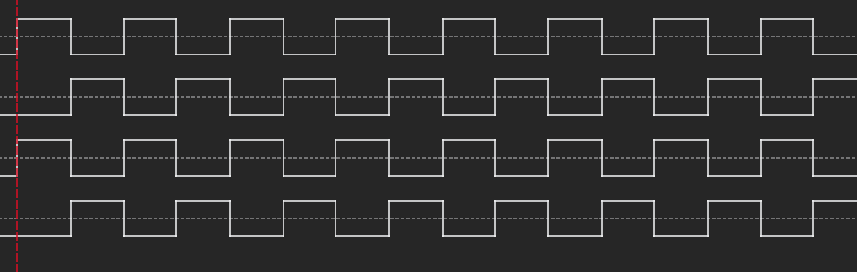
PWM modulation waveform in hardware position input mode: