69.6.6. UART LIN Slave Example
69.6.6.1. Overview
This example demonstrates how to use UART peripheral to simulate LIN slave functionality, including:
LIN slave receiving data from master
LIN slave responding to master’s data request
LIN enhanced checksum functionality
69.6.6.2. Working Principle
This example implements the following functions:
Receiving master data: - Receive LIN frame (ID: 0x31, Data: 0x0-0x7) - Verify data correctness
Responding to master request: - Send LIN frame (ID: 0x30, Data: 0x7-0x0) - Use enhanced checksum
69.6.6.3. Workflow
Initialization Process:
UART Initialization:
Configure baudrate
Enable line status interrupt for break detection
Configure frame format as 8-bit data, no parity
Frame Header Detection Process:
Break Detection:
Enable line status interrupt to detect break signal
Clear RX FIFO when break is detected
Configure RX FIFO trigger level to 1 byte for sync field and PID reception
Sync Field and PID Detection:
Receive and verify sync field (0x55)
Receive and verify PID checksum bits
Determine subsequent operation (send/receive) based on ID
Data Processing Flow:
Receiving Data (ID: 0x31):
Configure RX FIFO trigger level greater than remaining frame length
Enable RX timeout interrupt
Receive and verify data in interrupt
Sending Data (ID: 0x30):
Prepare response data (0x7-0x0)
Enable TX FIFO interrupt
Confirm data transmission completion in interrupt
Interrupt Handling Process:
Line Status Interrupt:
Detect break signal
Prepare for frame header reception
Configure reception parameters
RX Data Interrupt:
Receive sync field and PID
Verify data correctness
Configure subsequent operations
TX FIFO Interrupt:
Detect transmission completion
Note: When uart_intr_tx_slot_avail interrupt occurs, the last byte may still be in TX FIFO, additional status check or TXIDLE interrupt feature may be needed depending on version
RX Timeout Interrupt:
Receive complete data frame
Verify data correctness
Disable RX timeout interrupt
Note: RX timeout method requires interval between data frames ≥ 4 UART byte transmission time
69.6.6.4. Important Notes
Baudrate auto-detection is not supported, UART baudrate must be configured to the required value
Slave auto-sleep is not supported, no need for master wakeup
69.6.6.5. Hardware Requirements
One development board
One USB to LIN debugger
LIN transceiver (if not integrated on board)
69.6.6.6. Hardware Setup
Choose the appropriate connection method based on your board type:
For boards with onboard LIN transceiver:
Connect LIN signal line from USB-LIN debugger to board’s LIN signal pin
Connect GND
For boards without onboard LIN transceiver:
Connect board’s UART TX and RX pins to MCU side of LIN transceiver
Connect USB-LIN debugger to LIN bus side of transceiver
Connect GND
Please refer to Pin Description section for specific pin connections.
69.6.6.7. Running Steps
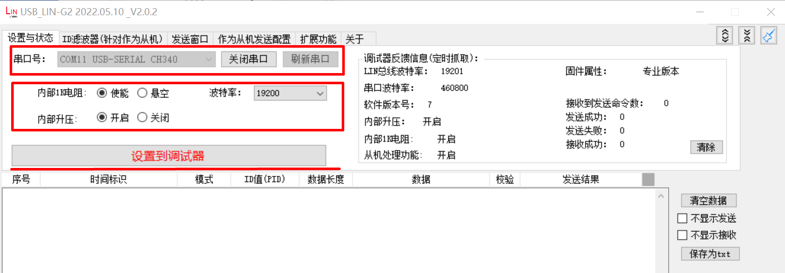
Configure USB-LIN debugger:
Select correct COM port and baudrate (19200)
Click “Set to Debugger” button
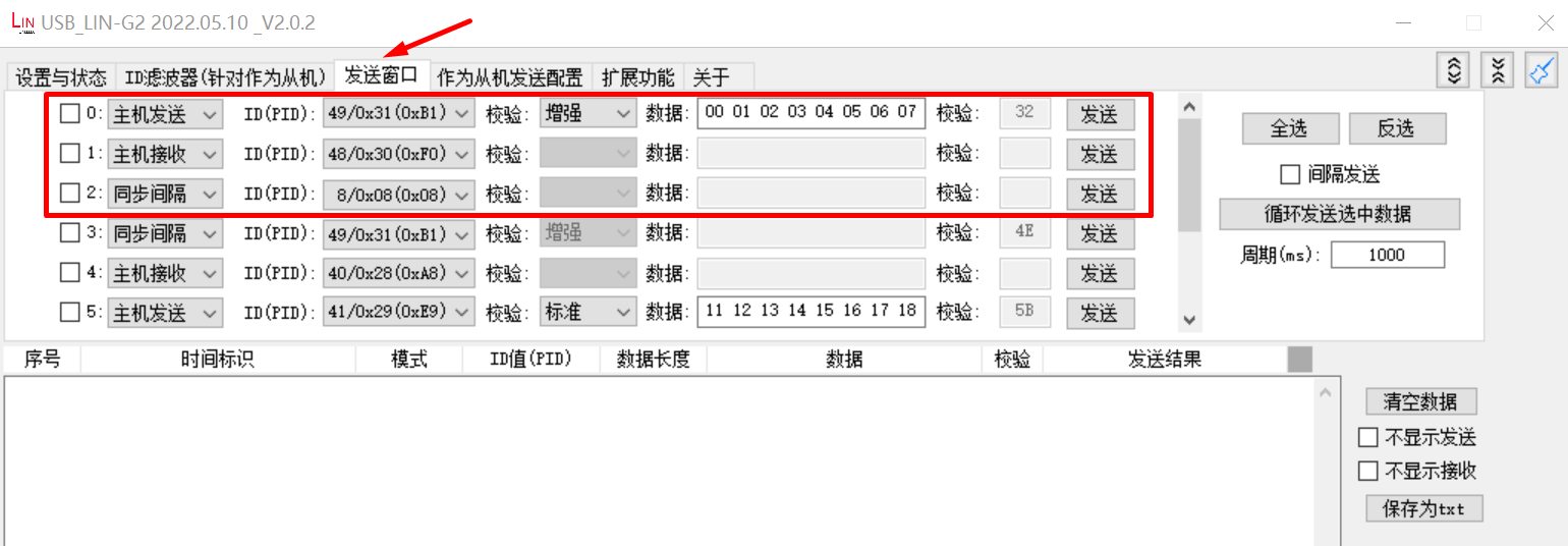
Configure master transmission:
Set ID to 0x31
Configure transmission data as: 0x0, 0x1, 0x2, 0x3, 0x4, 0x5, 0x6, 0x7
Select enhanced checksum
Enable the option
Click “Configure to Debugger” button
Compile and download the program to the board and run
69.6.6.8. Running Results
Terminal output:
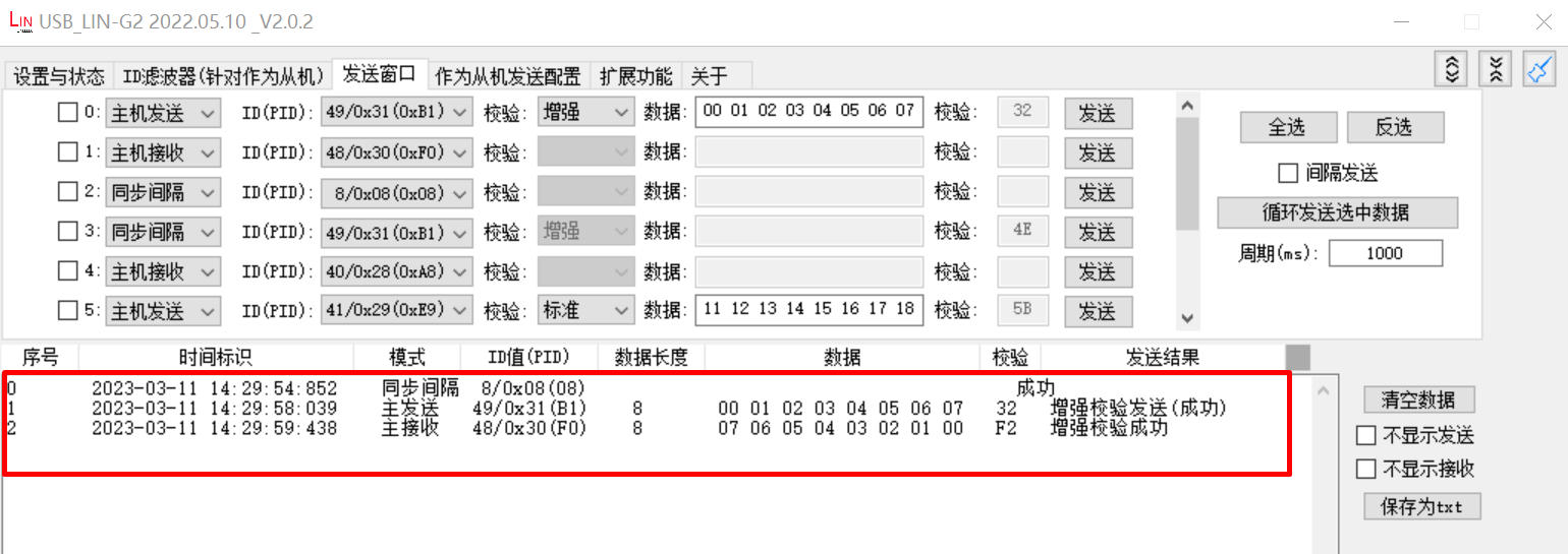
Test uart lin slave example
uart lin receive ID: 0x31
uart receive 8 data:
0x0 0x1 0x2 0x3 0x4 0x5 0x6 0x7
uart lin receive ID: 0x30
uart send 8 data:
0x7 0x6 0x5 0x4 0x3 0x2 0x1 0x0
USB-LIN debugger communication data display:
69.6.6.9. Debugging Suggestions
Hardware Connection Check
Use Logic Analyzer to observe LIN bus signals, verify the waveforms of break, sync, data section and checksum
When using interrupt mode, check if interrupts are generated as expected
When using polling mode, verify if the driver timeout settings match the data frame baudrate