2. HPM5301EVKLITE
2.1. Overview
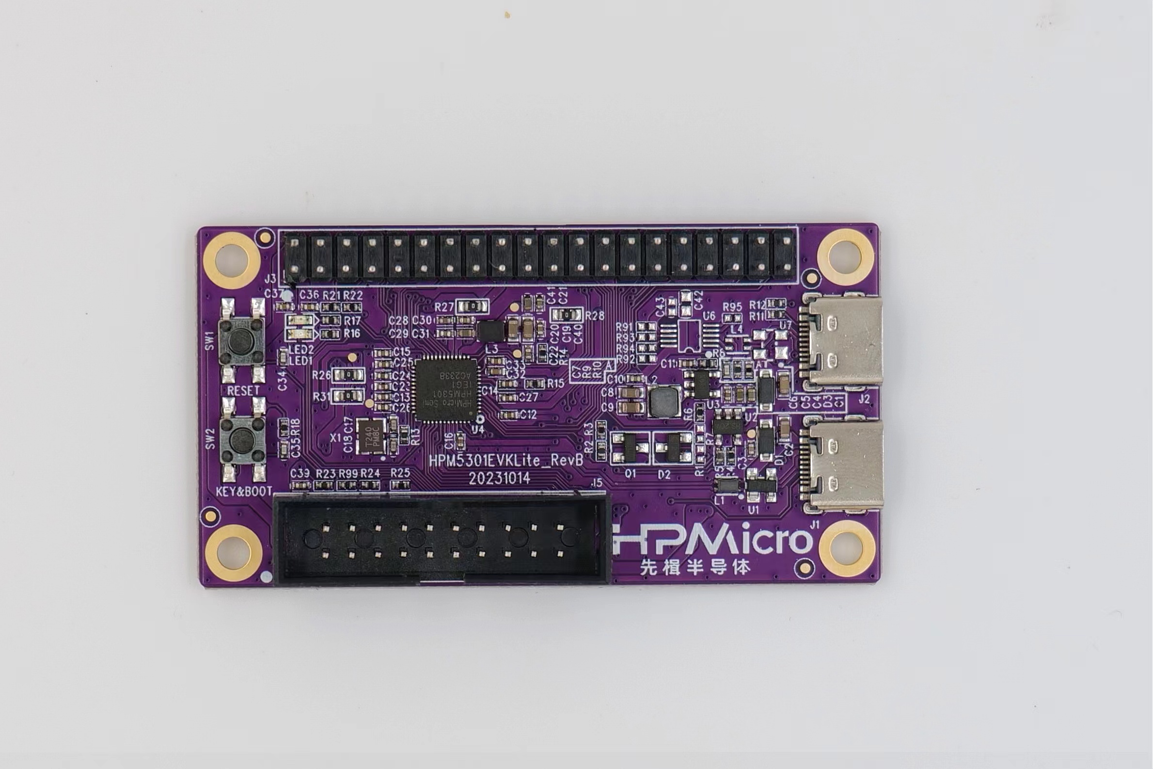
HPM5301EVKLite is a development board based on Xianji’s entry-level high-performance MCU HPM5301. HPM5301EVKLite provides a USB Type-C interface for high-speed USB-OTG functionality, with onboard buttons and LEDs for convenient user interaction. It also provides an extension interface that is compatible with Raspberry Pi and a standard JTAG debugging interface.
2.2. Console information printing
By default, UART0 is used for console printing. Connect UART0.TXD (J3.36) and UART0.RXD (J3.38) externally through the USB to serial port tool.
2.3. Boot Switch
The KEY&BOOT button controls the boot switch
By default, the board boots from flash
To enter ISP boot mode, follow these steps:
Press reset
Press key
Release reset
Release key
KEY |
Description |
|---|---|
OFF |
Boot from Quad SPI NOR flash |
ON |
ISP |
2.5. Pin Description
UART Pin: modbus_rtu sample - The UART0 used for debugger console or some functional testing using UART - The UART3 is used for some functional testing using UART, such as USB_CDC_ACM_UART, MODBUS_RTU etc.
Function |
Position |
Remark |
|---|---|---|
UART3.TXD |
J3[8] |
|
UART3.RXD |
J3[10] |
|
UART0.TXD |
J3[36] |
|
UART0.RXD |
J3[38] |
|
UART3.break |
J3[24] |
generate uart break signal |
SPI Pin:
Function |
Position |
|---|---|
SPI1.CSN |
J3[24] |
SPI1.SCLK |
J3[23] |
SPI1.MISO |
J3[21] |
SPI1.MOSI |
J3[19] |
I2C Pin:
Function |
Position |
|---|---|
I2C3.SCL |
J3[28] |
I2C3.SDA |
J3[27] |
ACMP Pin:
Function |
Position |
|---|---|
ACMP.CMP1.INN4 |
J3[13] |
ACMP.COMP_1 |
J3[3] |
ADC16 Pin:
Function |
Position |
|---|---|
ADC0.INA2 |
J3[26] |
ADC1.INA1 |
J3[3] |
TinyUF2 Pin:
Note
PA9 connect GND, and press reset, board enter DFU mode, then PA9 connect 3.3V, drag app to U disk, will download app and enter app directly if successfully;
PA9 connect 3.3V, and press reset, board enter bootloader mode, if flash has the valid app, will directly enter app;
Function |
Position |
|---|---|
TinyUF2 Button |
J3[32] |
GPTMR Pin:
Function |
Position |
Remark |
|---|---|---|
GPTMR0.CAPT_1 |
J3[3] |
SENT decode input pin (idle low level) |
GPTMR0.COMP_1 |
J3[5] |
|
GPTMR0.COMP_3 |
J3[8] |
BCLK of i2s emulation |
GPTMR0.COMP_2 |
J3[26] |
LRCK of i2s emulation |
GPTMR1.COMP_1 |
J3[7] |
MCLK of i2s emulation |
GPTMR0.CAPT_2 |
J3[11] |
SENT decode input pin (idle high level) |
CS Pin of i2s emulation
Function |
Position |
Remark |
|---|---|---|
PA31 |
J3[11] |
the pin that controls the SPI slave CS |
CLOCK REF Pin
Function |
Position |
|---|---|
PA09 |
J3[32] |
ESP-HOSTED Pin
Function |
Position |
Note |
|---|---|---|
PA09 |
J3[32] |
RESET Pin |
PB12 |
J3[27] |
HANDSHAKE Pin |
PB13 |
J3[28] |
DATA_READY Pin |
BROWNOUT Interrupt Indicator Pin
Function |
Position |
|---|---|
PB13 |
J3[28] |