7. DAC
7.1. Overview
This example shows DAC conversions and waveform display in three working modes.
7.2. Board Setting
Output voltage at the specified pin. (Please refer to Pin Description)
If necessary, connect a jumper for VREF pin according to the HW design. (Please refer to Pin Description)
7.3. Running the example
Running log is shown in the serial terminal as follows
This is a DAC demo:
1. Direct mode
2. Step   mode
3. Buffer mode
Please enter the DAC mode code:
Select one of DAC working modes to start DAC conversion, and then observe the waveform through an oscilloscope
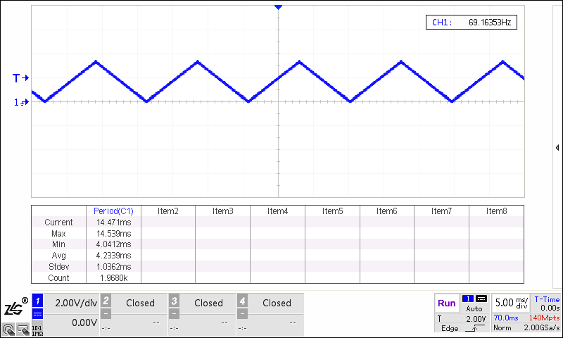
Direct mode
Please enter the DAC mode code: 1
Set DAC to output data in direct mode
DAC is outputting a triangle waveform in direct mode
Step mode
Please enter the DAC mode code: 2
Set DAC to output data in step mode
DAC is outputting a saw tooth waveform in step mode

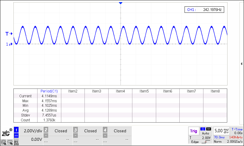
Buffer mode
Please enter the DAC mode code: 3
Set DAC to output data in buffer mode
DAC is outputting a sine waveform in buffer mode
7.4. Note
Exception exit
In step mode or in buffer mode, press the “space” key to abort the test, and then a test mode can be reselected.
In direct mode, press the “space” key to abort the loop after the test is finished, and then a test mode can be reselected.