3. HPM6300EVK
3.1. Overview
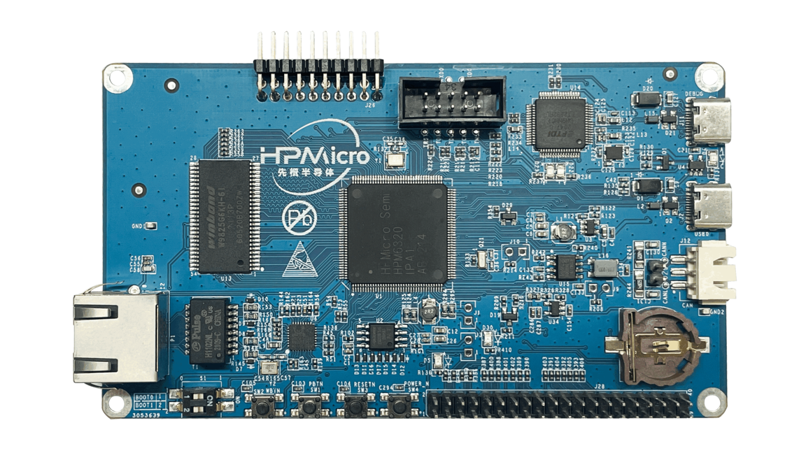
HPM6300EVK provides interfaces for most of the peripherals of the HPM6300 microcontroller, including 1 SD card slot, 1 USB Type-C interface, a 100M Ethernet port, CAN FD interface, etc., and expands NOR Flash, SDRAM and other external memories , and integrates an on-board debugger.
3.2. Hardware
HPM6360IPA MCU
Onboard Memory
16bit 256Mb SDRAM
128Mb Quad SPI NOR Flash
USB
USB type C (USB 2.0 OTG) connector x2
Ethernet
100Mb PHY
Others
TF Slot
CAN FD
FT2232
Expansion port
Motor control port
Raspberry PI extension port
Note
The sdram pins are multiplexed with the 15-20pin of the motor interface J26, so the motor interface and sdram can’t be used at the same time.
3.3. DIP Switch S1
Bit 1 and 2 controls boot mode
bit[2:1] |
Description |
|---|---|
OFF, OFF |
Boot from Quad SPI NOR flash |
OFF, ON |
Serial boot |
ON, OFF |
ISP |
3.5. Pin Description
SPI Pin:
Function |
Position |
|---|---|
SPI3.CSN |
J28[24] |
SPI3.SCLK |
J28[23] |
SPI3.MISO |
J28[21] |
SPI3.MOSI |
J28[19] |
I2C Pin:
Function |
Position |
|---|---|
I2C0.SCL |
J28[13] |
I2C0.SDA |
J28[15] |
ACMP Pin
Function |
Position |
|---|---|
CMP.INN5 |
J26[7] |
CMP.COMP_1 |
J26[8] |
GPTMR Pin
Function |
Position |
Remark |
|---|---|---|
GPTMR2.CAPT_0 |
J28[40] |
|
GPTMR2.COMP_0 |
J28[35] |
MCLK of i2s emulation |
GPTMR2.COMP_1 |
J28[12] |
LRCK of i2s emulation |
GPTMR2.COMP_2 |
J28[16] |
BLCK of i2s emulation |
ADC16 Pin
Function |
Position |
|---|---|
ADC16 Reference Voltage |
J108[2] |
ADC0.INA6 |
J28[38] |
DAC Pin
Function |
Position |
|---|---|
DAC Reference Voltage |
J108[2] |
DAC0.OUT |
J26[11] |
PWM Pin
Function |
Position |
|---|---|
PWM2.P0 |
J26[14] |
PWM2.P1 |
J26[13] |
Ethernet PPS Pin
Function |
Pin |
Position |
|---|---|---|
ENET0.EVTO0 |
PC21 |
J28[19] |
ENET0.EVTO1 |
PC20 |
J28[23] |
ENET0.EVTI0 |
PC27 |
J28[22] |
ENET0.EVTI1 |
PC26 |
J28[18] |
UART pin
The UART2 is used for some functional testing using UART, such as uart_software_rx_idle, uart_rx_timeout, uart_software_lin, MICROROS_UART, USB_CDC_ACM_UART, MODBUS_RTU etc.
Function |
Position |
Remark |
|---|---|---|
UART2.TXD |
J28[18] |
|
UART2.RXD |
J28[22] |
|
UART2.break |
J28[24] |
generate uart break signal |
TRGMUX pin for uart_software_rx_idle sample
Function |
Position |
|---|---|
TRGM1_P4(PA24) |
J28[16] |
Motor Pin:
Refer to section DRV-LV50A-MP1907 Motor Driver Board for configuration
Tamper Pin
Function |
Pin |
Position |
Mode |
|---|---|---|---|
TAMP.06 |
PZ06 |
J28[8] |
Active Mode |
TAMP.07 |
PZ07 |
J28[10] |
Active Mode |
CS Pin of i2s emulation
Function |
Position |
Remark |
|---|---|---|
PA07 |
J28[11] |
the pin that controls the SPI slave CS |