7. HPM6800EVK
7.1. Overview
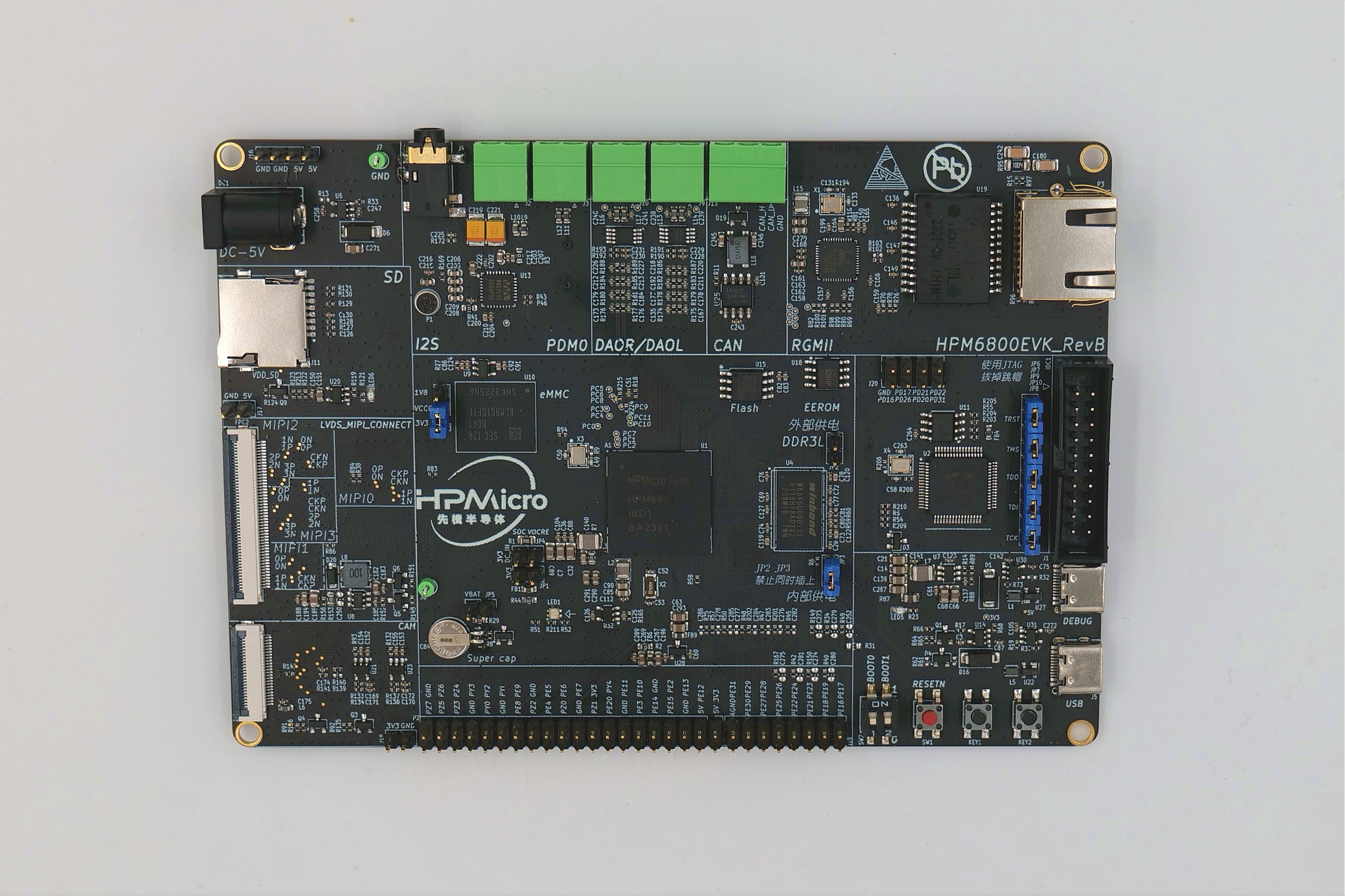
The HPM6800 is a single-core flashless MCU running 600Mhz. It has a 1MB continuous on-chip ram. Also, it provides various memory interfaces, including SDRAM, Quad SPI NOR Flash, SD/eMMC. It integrates rich audio and video interfaces, including LCD, pixel DMA, camera, and I2S audio interfaces.
7.2. Hardware
HPM6800 MCU (600MHz, 1MB SRAM)
Onboard Memory
512MB SDRAM (DDR3L 16bits)
16MB Quad SPI NOR Flash
16GB eMMC
Display & Camera
LCD connector
MIPI-DSI
MIPI-CSI
Camera (DVP)
Ethernet
1000 Mbits PHY
USB
USB type C (USB 2.0 OTG) connector x1
Audio
Line in
Mic
DAO
Others
TF Slot
RGB LED
CAN
7.3. DIP Switch SW2
Bit 1 and 2 controls boot mode
bit[2:1] |
Description |
|---|---|
OFF, OFF |
Boot from Quad SPI NOR flash |
OFF, ON |
Boot from eMMC |
ON, OFF |
ISP |
7.5. Plug-in
The ADC/DAC reference voltage is selected as follows:
Connection
Description
J18
Reference voltage
The eMMC voltage is sleected as follows:
Connection
Description
J6
eMMC voltage selection (3.8V / 1.8V)
Note: User should short VCCQ and 1.8V pin for eMMC testing
7.6. Pin Description
UART0 Pin:
The UART0 use for debugger console:
Function |
Pin |
Position |
|---|---|---|
UART0.TX |
PA00 |
DEBUGUART0 |
UART0.RX |
PA01 |
DEBUGUART0 |
UART3 Pin:
The UART3 is used for some functional testing using UART, such as MICROROS_UART, USB_CDC_ACM_UART, MODBUS_RTU etc.
Function |
Pin |
Position |
Remark |
|---|---|---|---|
UART3.TX |
PE15 |
P2[8] |
|
UART3.RX |
PE14 |
P2[10] |
|
UART3.break |
PE04 |
P2[24] |
generate uart break signal |
PUART Pin:
The PUART is used for low power mode testing, such as wakeup, etc.
Function |
Pin |
Position |
|---|---|---|
PUART.TX |
PY00 |
P2[32] |
PUART.RX |
PY01 |
P2[29] |
SPI Pin:
Function |
Pin |
Position |
|---|---|---|
SPI3.CSN |
PE04 |
P2[24] |
SPI3.SCLK |
PE05 |
P2[23] |
SPI3.MISO |
PE06 |
P2[21] |
SPI3.MOSI |
PE07 |
P2[19] |
I2C Pin::
Function |
Pin |
Position |
|---|---|---|
I2C1.SCL |
PE13 |
P2[5] |
I2C1.SDA |
PE12 |
P2[3] |
ADC16 Pin
Function |
Pin |
Position |
|---|---|---|
ADC0.INA8 |
PE16 |
J19[15] |
GPTMR Pin
Function |
Pin |
Position |
Remark |
|---|---|---|---|
GPTMR2.CAPT_0 |
PE22 |
J19[9] |
|
GPTMR2.COMP_0 |
PE23 |
J19[12] |
MCLK of i2s emulation |
GPTMR2.COMP_1 |
PE24 |
J19[10] |
LRCK of i2s emulation |
GPTMR2.COMP_2 |
PE26 |
J19[8] |
BLCK of i2s emulation |
headphone interface
Function |
Position |
Standard |
|---|---|---|
3.5mm headphone |
J4 |
OMTP |
audio input interface
Function |
Position |
|---|---|
microphone |
P1 |
DAO interface
Function |
Position |
|---|---|
DAO-SPK(left) |
J9 |
DAO-SPK(right) |
J10 |
Ethernet PPS Pin
Function |
Pin |
Position |
|---|---|---|
ENET0.EVTO0 |
PD31 |
J20[7] |
ENET0.EVTO1 |
PE10 |
P2[11] |
ENET0.EVTI0 |
PE17 |
J19[16] |
ENET0.EVTI1 |
PE19 |
J19[14] |
CAN Pin
Function |
Pin |
Position |
Output |
|---|---|---|---|
MCAN3.TXD |
PD15 |
U25[1] |
CAN.H J13[3] |
MCAN3.RXD |
PD14 |
U25[4] |
CAN.L J13[2] |
MCAN3.STBY |
PD13 |
U25[8] |
Tamper Pin
Function |
Pin |
Position |
Mode |
|---|---|---|---|
TAMP.04 |
PZ04 |
P2[35] |
Active Mode |
TAMP.05 |
PZ05 |
P2[38] |
Active Mode |
TAMP.06 |
PZ06 |
P2[37] |
Passive Mode |
CS Pin of i2s emulation
Function |
Position |
Remark |
|---|---|---|
PE27 |
J19[5] |
the pin that controls the SPI slave CS |