51.1. Compare Point Matching
51.1.1. Overiew
PWM supports modifying the pwm waveform at any time within a period. This project demonstrates the modification of the pwm waveform at the zero point and the reload point within the period and outputs it through the corresponding pins of the MCU.
51.1.2. Configurations
Oscilloscope
Install the serial terminal, view board information , and configure the serial terminal parameters
PWM_P0, PWM_P2, PWM_P4 pins Check the information according to the board model
51.1.3. Running the Demo
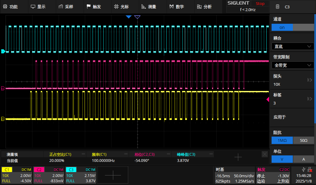
After power-on, three outputs can be observed through an oscilloscope. The output of P0 is triggered by zero-point matching, the output of P2 is triggered by reload-point matching, and the output of P4 is a center-aligned waveform, which is used as a reference waveform.
After every 10 waveforms are output from P0 and P2, the PWM output waveforms are modified at the matching points.
Serial port printing information:
pwmv2 point trigger example
choose PWM output channel [P0 P2 P4]


>> P0 and P2 generate pwm waveform P4 is reference
Modify the duty cycle at the midpoint when generating the 11th pulse
duty cycle will be updated from 0 - 100 and back to 0, the step size is 20%
The obtained waveforms are shown in the figure
The yellow one is the output of P0<br> The pink one is the output of P2<br> The blue one is the output of P4