69.5. uart_lin_master
69.5.1. Overview
This project demonstrates the functionality of UART simulation LIN master.
69.5.2. Note
The interval between LIN frames should be greater than or equal to the transmission time of 4 UART bytes。
69.5.3. Board Setting
On development boards without onboard LIN transceivers:
Need a LIN transceiver and a USB_LIN debugger Connect the UART TX/RX pins on the development board to the TX/RX signal of the LIN transceiver, and connect the USB_LIN debugger to the LIN signal of the LIN transceiver.
On development boards with onboard LIN transceivers:
Need a USB_LIN debugger Connect the LIN signal and GND of the debugger to the corresponding pins on the development board.
Please refer to Pin Description for specific board.
69.5.4. Running the example
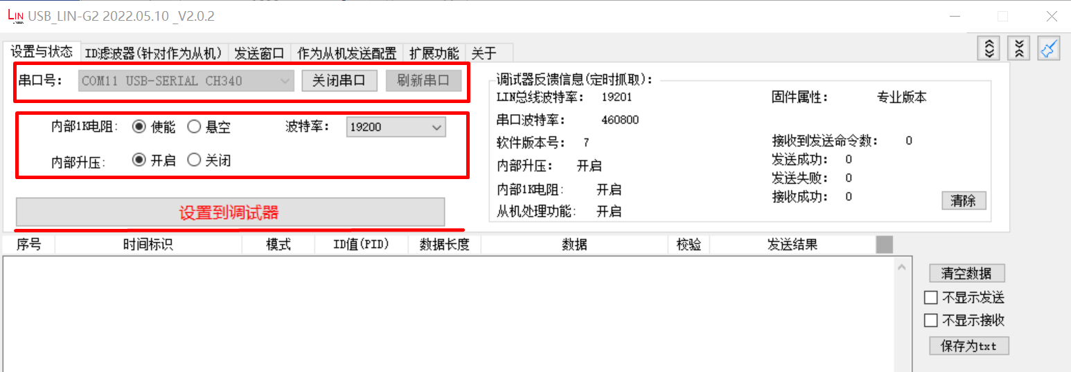
Configure usb_lin debugger: - Configure com and baudrate, then click Set to Debugger option
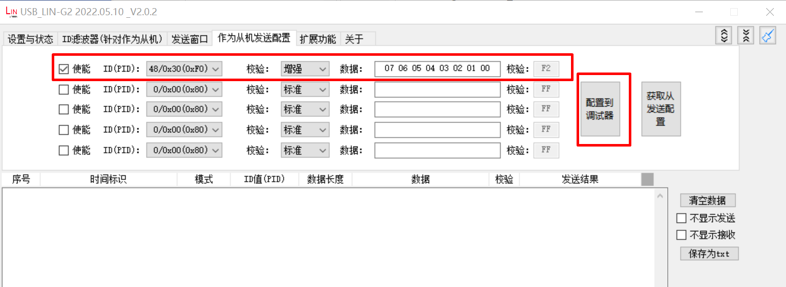
Set ID, data and checksum mode, tick enable option, then click Configure to Debugger option:
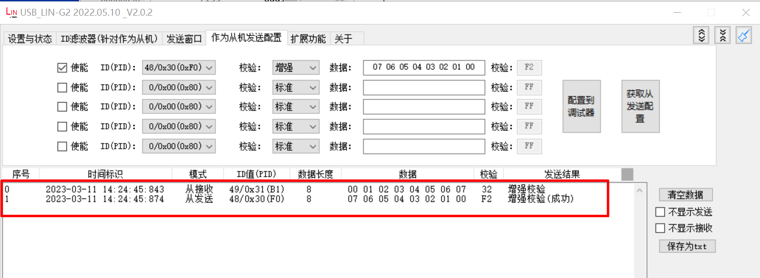
Running the example, check the result in debugger window
When the example runs successfully, the log would be seen on the terminal like:
Test uart lin master polling transfer
uart lin master send ID: 0x31
uart send 8 data:
0x0 0x1 0x2 0x3 0x4 0x5 0x6 0x7
uart lin master send ID: 0x30
uart receive 8 data:
0x7 0x6 0x5 0x4 0x3 0x2 0x1 0x0

Test uart lin master interrupt transfer
uart lin master send ID: 0x31
uart send 8 data:
0x0 0x1 0x2 0x3 0x4 0x5 0x6 0x7
uart lin master send ID: 0x30
uart receive 8 data:
0x7 0x6 0x5 0x4 0x3 0x2 0x1 0x0