65.10. uart_lin_slave_baudrate_adaptive
65.10.1. Overview
This project demonstrates the use of PLB to detect LIN baudrate and UART as LIN slave achieves adaptive transmission and reception of LIN frame.
65.10.2. Note
The interval between data frames should be greater than or equal to the transmission time of 4 UART bytes.
The slave automatic sleep function is not supported, the master no need to wake up slave.
65.10.3. Board Setting
On development boards without onboard LIN transceivers: Need a LIN transceiver and a USB_LIN debugger Connect the UART TX/RX pins on the development board to the TX/RX signal of the LIN transceiver, and connect the USB_LIN debugger to the LIN signal of the LIN transceiver.
On development boards with onboard LIN transceivers: Need a USB_LIN debugger Connect the LIN signal and GND of the debugger to the corresponding pins on the development board.
connect the UART RX pin to the PLB LIN clock detection pin to achieve PLB monitoring of LIN baudrate.
Please refer to Pin Description for specific board.
65.10.4. Running the example
configure usb_lin debugger:
configure com and baudrate, then click
Set to Debuggeroption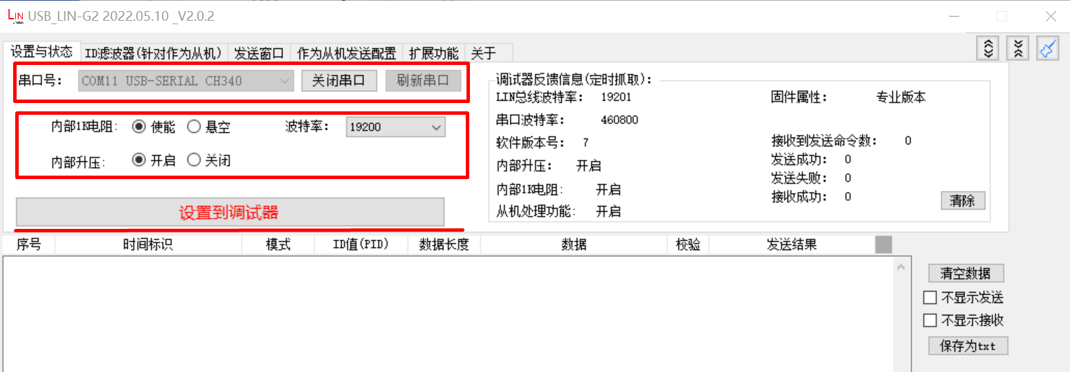
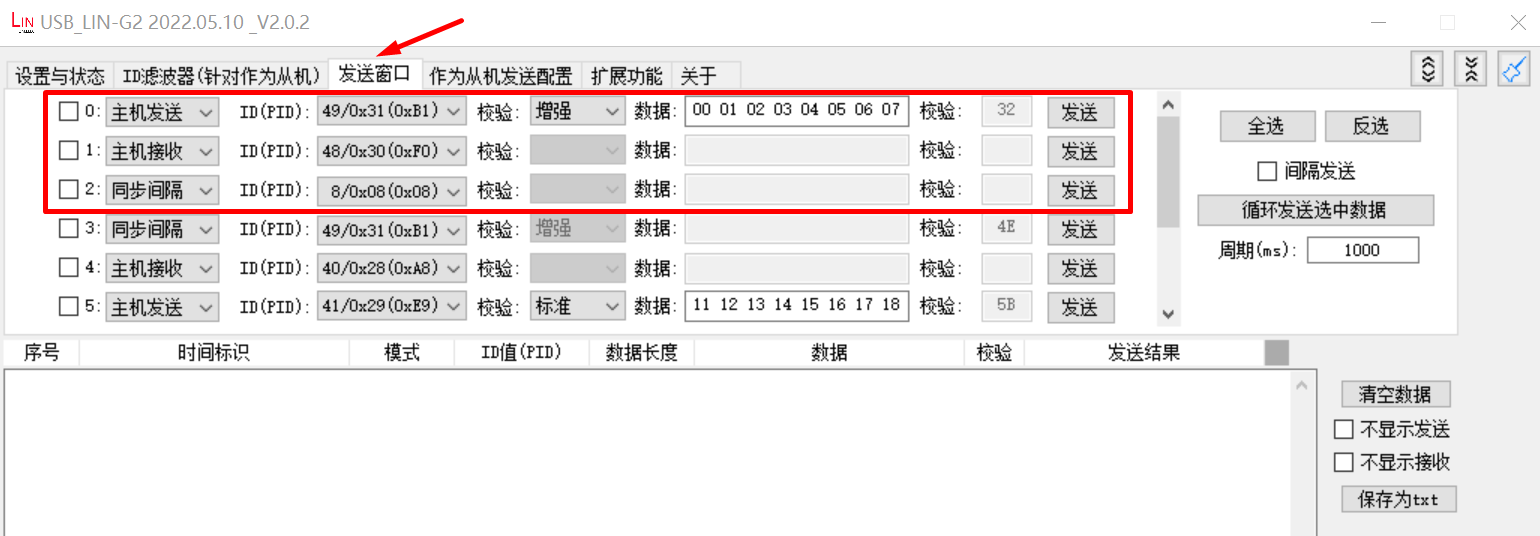
Configure sent data, including master sent, master receive:
Running the example, check the result in debugger window
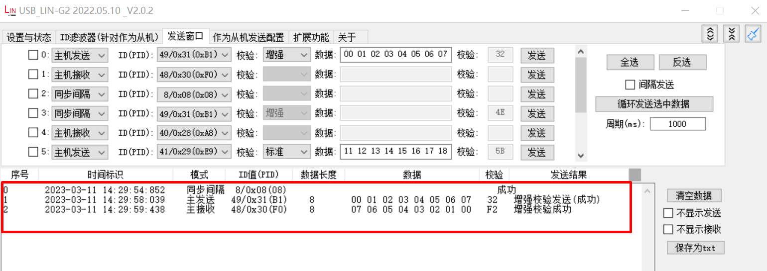
When the example runs successfully, using the USB_LIN debugger to send data frames, the serial terminal will output the following information. Adjust the LIN baud rate in the debugger, and the program will also receive it correctly:
Test uart lin slave baudrate adaptive example
uart lin receive ID: 0x31
uart receive 8 data:
0x0 0x1 0x2 0x3 0x4 0x5 0x6 0x7
uart lin receive ID: 0x30
uart send 8 data:
0x7 0x6 0x5 0x4 0x3 0x2 0x1 0x0