1. HPM5300EVK
1.1. Overview
The HPM5300EVK provides a series of interfaces for the characteristic peripherals of the HPM5300 series microcontrollers, including an ADC input SMA interface, a first-class motor control interface, an ABZ output interface, and an RS485/422 interface. HPM5300EVK also integrates one 2x20 pin IO expansion interface, which connects most of the IOs of the HPM5300 MCU for users to freely evaluate. HPM5300EVK expands NOR Flash storage for MCU and integrates an on-board debugger.
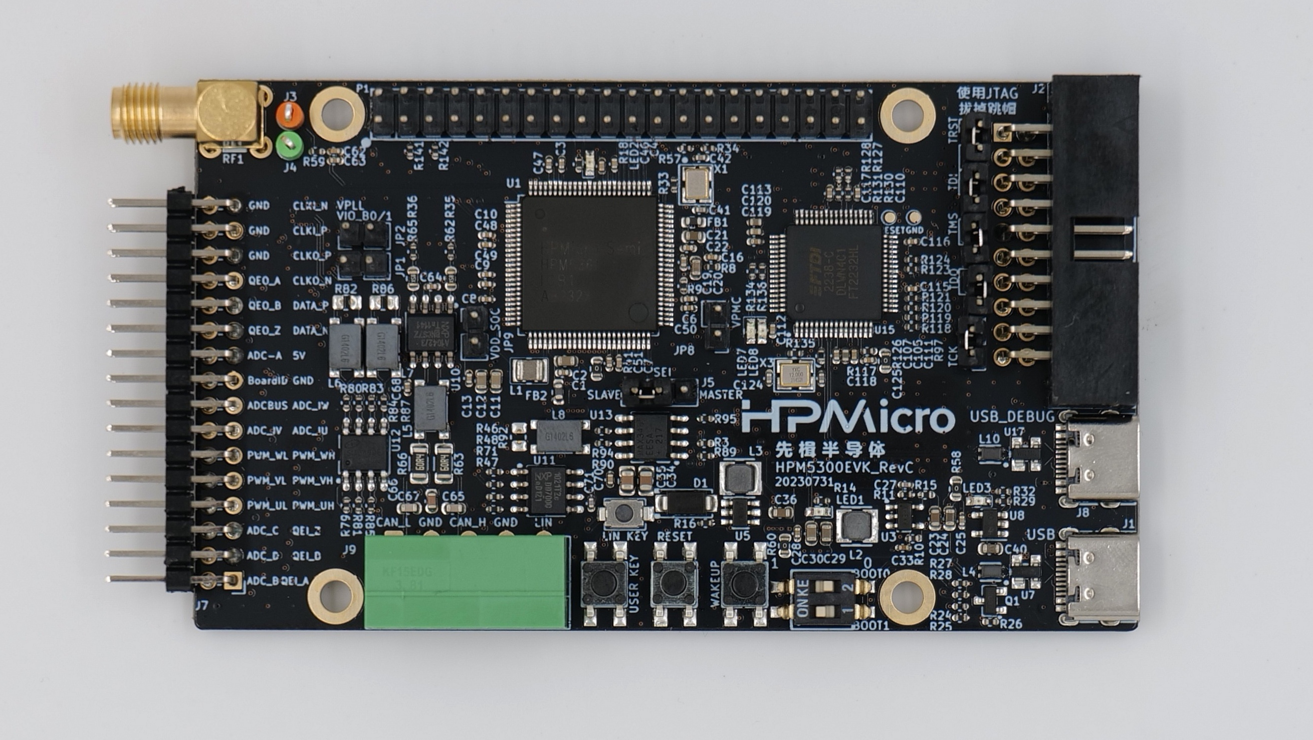
1.2. DIP Switch
Bit 1 and 2 control boot mode
bit[2:1] |
Description |
|---|---|
OFF, OFF |
Boot from Quad SPI NOR flash |
OFF, ON |
Serial boot |
ON, OFF |
ISP |
1.4. Pin Description
UART Pin: modbus_rtu sample
The UART2 is used for some functional testing using UART, such as MICROROS_UART, USB_CDC_ACM_UART, etc.
Function |
Position |
Remark |
|---|---|---|
UART2.TXD |
P1[8] |
|
UART2.RXD |
P1[10] |
|
UART2.DE |
P1[38] |
|
UART2.break |
P1[24] |
generate uart break signal |
LIN Pin (UART_LIN case):
Function |
Position |
|---|---|
LIN |
J9[5] |
SPI Pin:
Function |
Position |
|---|---|
SPI1.CSN |
P1[24] |
SPI1.SCLK |
P1[23] |
SPI1.MISO |
P1[21] |
SPI1.MOSI |
P1[19] |
I2C Pin:
Function |
Position |
|---|---|
I2C0.SCL |
P1[28] |
I2C0.SDA |
P1[27] |
ACMP Pin:
Function |
Position |
|---|---|
ACMP.CMP1.INN4 |
J7[4] |
ACMP.COMP_1 |
J7[2] |
GPTMR Pin:
Function |
Position |
Remark |
|---|---|---|
GPTMR0.CAPT_0 |
P1[3] |
|
GPTMR0.COMP_0 |
P1[5] |
BLCK of i2s emulation |
GPTMR0.COMP_1 |
P1[8] |
LRCK of i2s emulation |
GPTMR0.COMP_3 |
J7[18] |
MCLK of i2s emulation |
ADC16 Pin:
Function |
Position |
Remark |
|---|---|---|
ADC0.INA13 |
P1[32] |
ADC16 |
DAC Pin:
Function |
Position |
|---|---|
DAC0.OUT |
J7[20] |
DAC1.OUT |
J7[2] |
PWM Pin:
Function |
Position |
|---|---|
PWM0.P2 |
J7[11] |
PWM0.P3 |
J7[12] |
PLB Pulse Output Pin:
Function |
Position |
|---|---|
PLB.PLUSE_OUT |
P1[24] |
PLB Filter Output Pin:
Function |
Position |
|---|---|
PLB.FILTER_IN |
J7[9] |
PLB.FILTER_OUT |
J7[11] |
CAN Pin:
Function |
Position |
|---|---|
CAN_L |
J9[1] |
CAN_H |
J9[3] |
OPAMP Pin:
Function |
Position |
|---|---|
OPAMP.OUT |
RF1 |
OPAMP.IN |
P1[31] |
RDC Pin:
Function |
evk Position |
RDC Position |
|---|---|---|
RDC.PWM |
J7[9] |
J2[7] |
RDC.ADC0 |
J7[13] |
J2[13] |
RDC.ADC1 |
J7[14] |
J2[14] |
GND |
J7[32] |
J2[17] |
QEO ABZ Pin:
Function |
Position |
|---|---|
QEO0.A |
J7[26] |
QEO0.B |
J7[24] |
QEO0.Z |
J7[22] |
PWM pin with QEO control:
Function |
EVK Position |
HPMicro’s stepper drive board Position |
|---|---|---|
PWM0.P2 |
J7[11] |
PWM_A1(J8[9]) |
PWM0.P3 |
J7[12] |
PWM_A2(J8[10]) |
PWM0.P4 |
J7[9] |
PWM_B1(J8[11]) |
PWM0.P5 |
J7[10] |
PWM_B2(J8[12]) |
SEI Pin:
Function |
Position |
|---|---|
SEI1.CLKI_N |
J7[31] |
SEI1.CLKI_P |
J7[29] |
SEI1.CLKO_P |
J7[27] |
SEI1.CLKO_N |
J7[25] |
SEI1.DATA_P |
J7[23] |
SEI1.DATA_N |
J7[21] |
SEI CLK Section:
Function |
Position |
Note |
|---|---|---|
SEI1.CLK Section |
J5 |
Master side, CLKO active. Slave side, CLKI active |
QEIV2 Sin/Cos Pin:
Function |
Position |
Remark |
|---|---|---|
ADC0.INA4 |
J7[15] |
ADC_IW (Cos) |
ADC1.INA5 |
J7[13] |
ADC_IU (Sin) |
Motor Pin:
Refer to section DRV-LV50A-MP1907 Motor Driver Board for configuration
CS Pin of i2s emulation:
Function |
Position |
Remark |
|---|---|---|
PA11 |
P1[16] |
the pin that controls SPI slave CS |
1.5. Board Know Issue
USB VBUS pin resistance issue
Impact
This issue may affect the Host’s ability to enumerate USB as a device.
Solution
Replace the 1kohm resistors R37 with 10ohm resistors.
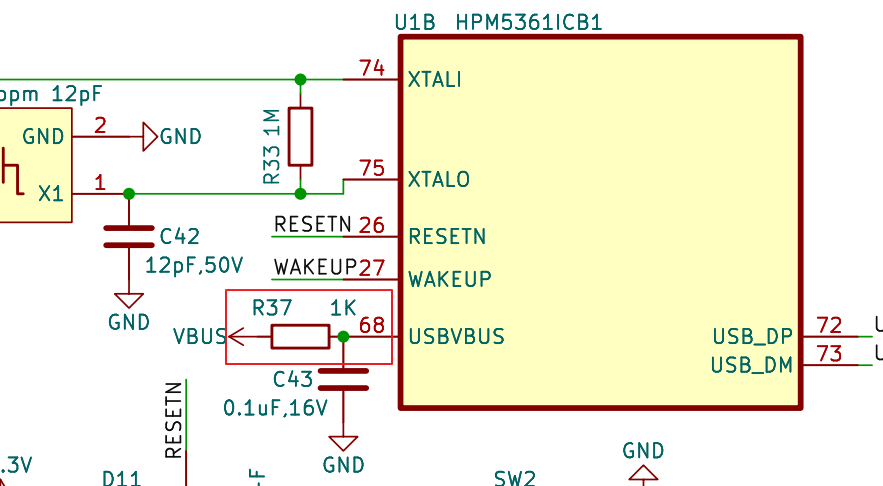
Revised Status
HPM5300EVKRevD has been revised, HPM5300EVKRevC and previous versions have this issue.