6. HPM6750EVKMINI
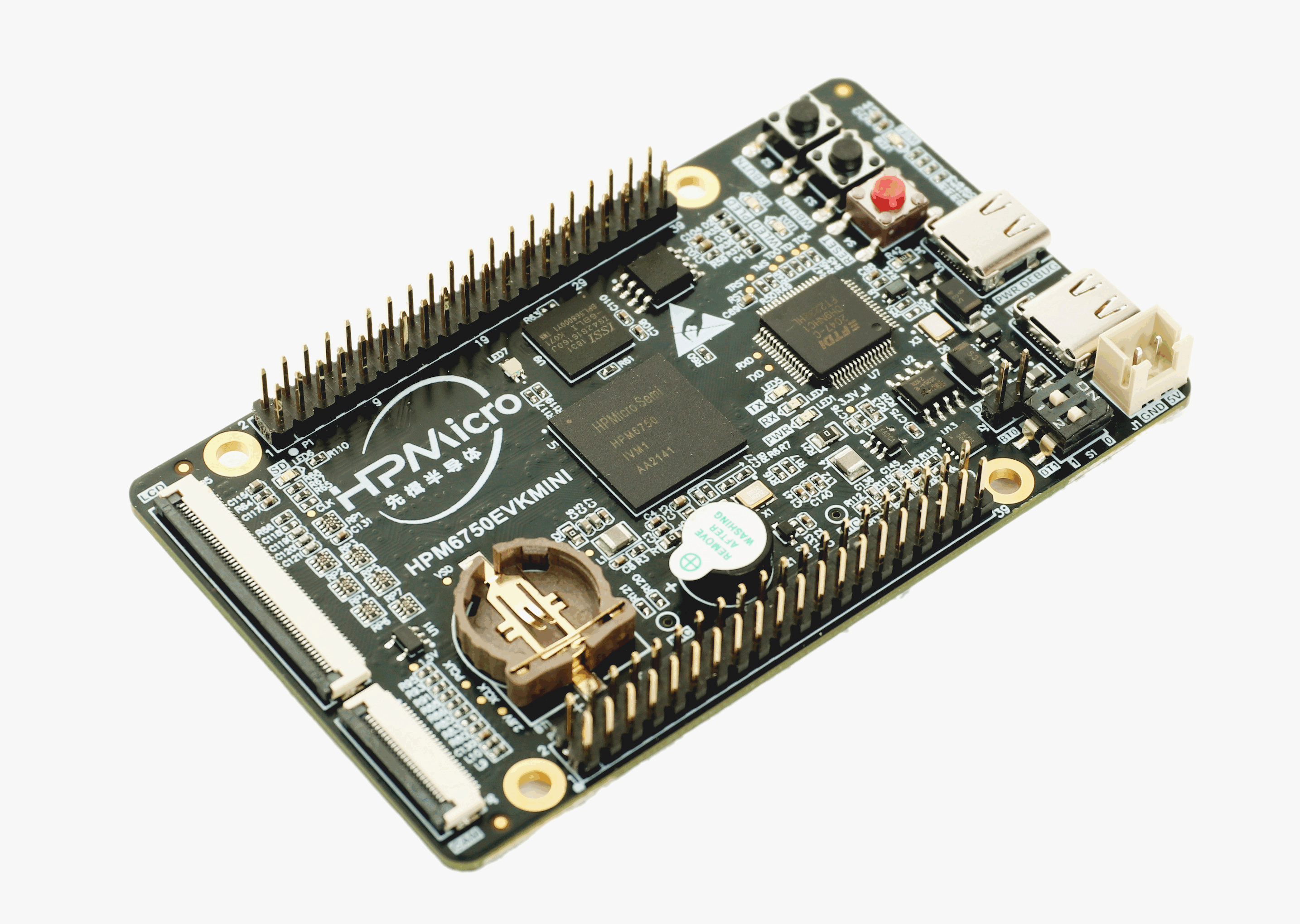
6.1. Overview
The HPM6750 is a dual-core flashless MCU running 816Mhz. It has a 2MB continuous on-chip ram. Also, it provides various memory interfaces, including SDRAM, Quad SPI NOR Flash, SD/eMMC. It integrates rich audio and video interfaces, including LCD, pixel DMA, camera, and I2S audio interfaces.
6.2. Hardware
HPM6750IVM MCU (816Mhz, 2MB OCRAM)
Onboard Memory
128Mb SDRAM
64Mb Quad SPI NOR Flash
Display & Camera
LCD connector
Camera (DVP)
WiFi
RW007 over SPI
USB
USB type C (USB 2.0 OTG) connector x2
Audio
Mic
DAO
Others
TF Slot
FT2232
Beeper
RGB LED
Expansion port
ART-PI extension port
6.3. DIP Switch S1
bit[2:1] |
Description |
|---|---|
OFF, OFF |
Boot from Quad SPI NOR flash |
OFF, ON |
Serial boot |
ON, OFF |
ISP |
6.5. Pin Description
SPI Pin
Function |
Position |
|---|---|
SPI2.CSN |
P1[24] |
SPI2.SCLK |
P1[23] |
SPI2.MISO |
P1[21] |
SPI2.MOSI |
P1[19] |
I2C Pin
Function |
Position |
|---|---|
I2C0.SCL |
P1[13] |
I2C0.SDA |
P1[15] |
UART for core1 debug console
Function |
Position |
Remark |
|---|---|---|
UART13.TXD |
P1[8] |
|
UART13.RXD |
P1[10] |
|
UART13.break |
P1[24] |
generate uart break signal |
ACMP Pin
Function |
Position |
|---|---|
CMP.INN6 |
P2[11] |
CMP.COMP_1 |
P1[7] |
GPTMR Pin
Function |
Position |
Remark |
|---|---|---|
GPTMR5.CAPT_1 |
P1[12] |
|
GPTMR5.COMP_0 |
P1[31] |
MCLK of i2s emulation |
GPTMR5.COMP_1 |
P1[35] |
LRCK of i2s emulation |
GPTMR5.COMP_2 |
P2[38] |
BLCK of i2s emulation |
ADC12 Pin
Function |
Position |
|---|---|
ADC12 Reference Voltage Setting |
N/A |
ADC0.VINP14 |
P1[33] |
ADC16 Pin
Function |
Position |
|---|---|
ADC16 Reference Voltage Setting |
N/A |
ADC3.INA2 |
P1[16] |
PWM Pin
Function |
Position |
|---|---|
PWM0.P4 |
P1[29] |
PWM0.P5 |
P1[32] |
DAO interface
Function |
Position |
|---|---|
Speaker |
J2 |
I2S pin
Function |
Position |
|---|---|
I2S0.FCLK |
P1[35] |
I2S0.BCLK |
P1[12] |
I2S0.RXD1 |
P1[38] |
I2S0.TXD1 |
P1[40] |
GND |
P1[39] |
Ethernet PPS Pin
Function |
Pin |
Position |
|---|---|---|
ENET0.EVTO0 |
PF05 |
P1[38] |
ENET0.EVTO1 |
PF06 |
P1[12] |
ENET0.EVTO2 |
PF09 |
P1[35] |
ENET0.EVTI0 |
PF00 |
P1[26] |
ENET0.EVTI1 |
PF01 |
P1[27] |
ENET0.EVTI2 |
PF02 |
P1[28] |
UART13 pin
The UART13 is used for core1 debug console or some functional testing using UART, such as uart_software_rx_idle, uart_rx_timeout, uart_software_lin, MICROROS_UART, USB_CDC_ACM_UART, MODBUS_RTU etc.
Function |
Position |
|---|---|
UART13.TXD |
P1[8] |
UART13.RXD |
P1[10] |
TRGMUX pin for uart_software_rx_idle sample
Function |
Position |
|---|---|
TRGM2_P9 (PD19) |
P2[35] |
Motor Pin
Refer to section HPM6750EVKMINI-TO-Motor Motor Expansion Board for configuration
Tamper Pin
Function |
Pin |
Position |
Mode |
|---|---|---|---|
TAMP.08 |
PZ08 |
P1[10] |
Active Mode |
TAMP.09 |
PZ09 |
P1[8] |
Active Mode |
TAMP.10 |
PZ10 |
P1[22] |
Passive Mode |
CS Pin of i2s emulation
Function |
Position |
Remark |
|---|---|---|
PD25 |
P2[40] |
the pin that controls the SPI slave CS |
6.6. Known Issues
Some samples may enter the trap handler during runtime, with a MCAUSE == 2 (instruction error). This is due to a flaw in ILM, as detailed in the Errata Manual E00001.
Solution: Change the ILM interface address in the link script to ILM_SLV address.